| Issue |
Eur. Phys. J. Appl. Phys.
Volume 100, 2025
|
|
|---|---|---|
| Article Number | 33 | |
| Number of page(s) | 16 | |
| DOI | https://doi.org/10.1051/epjap/2025033 | |
| Published online | 23 December 2025 | |
https://doi.org/10.1051/epjap/2025033
Tutorial Review
Modeling of inductive power transfer systems - a tutorial review
1
The Yangtze Delta Region Institute of the University of Electronic Science and Technology of China, 324000 Quzhou, P.R. China
2
Université Paris-Saclay, CentraleSupélec, CNRS, Laboratoire de Génie Electrique et Electronique de Paris, 91192 Gif-sur-Yvette, France
3
Sorbonne Université, CNRS, Laboratoire de Génie Electrique et Electronique de Paris, 75252 Paris, France
4
School of Life Science and Technology, and with the Brain-Computer Interface & Brain-Inspired Intelligence Key Laboratory of Sichuan Province, University of Electronic Science and Technology of China, 611731 Chengdu, P.R. China
* e-mail: This email address is being protected from spambots. You need JavaScript enabled to view it.
Received:
15
September
2025
Accepted:
27
November
2025
Published online: 23 December 2025
Abstract
Wireless power transfer systems, particularly those based on inductive coupling, provide an increasingly attractive way to deliver power without any physical connection or cables. There exists now a large literature about the topic, but generally each paper focuses on a single application and/or a typical design procedure or modeling technique. Since the covered published works belong to a variety of approaches, it can be a difficult task to understand the underlying physical aspects and modeling approaches, particularly for a newcomer to the field. This tutorial paper reviews and describes basic aspects required to model an inductive power transfer system, with a focus on practicality. The article is based on the author's work over a period of 10 yr. It introduces and explains the published methods and principles relevant to all aspects of an inductive link, such that no specific prior knowledge about wireless power transfer is required. The objectives can be divided into three main contributions: 1) To provide fundamental equations and basic principles of inductive power transfer, which are required to begin a design process; 2) To present these typical applications related to three levels of transferred power: electric vehicle (high power); drone (mid power) and biomedical implant (low power) to describe a large overview of practical systems; 3) To give newcomers to the topic an introduction to the modeling process and key aspects to facilitate any design process.
Key words: Inductive power transfer / electromagnetic analysis / design and optimization
© S. Ding et al., Published by EDP Sciences, 2025
 This is an Open Access article distributed under the terms of the Creative Commons Attribution License (https://creativecommons.org/licenses/by/4.0), which permits unrestricted use, distribution, and reproduction in any medium, provided the original work is properly cited.
1 Introduction
Wireless power transfer (WPT) technologies have now reached a commercial stage in applications going from consumer electronics (smartphones, laptops, tablets, etc.), electromobility, biomedical implants and domestic applications. Today, this definition covers several technologies in a widespread range of applications, powers and distances [1,2]. Wireless power transfer technologies based on electromagnetic fields can be divided into two categories according to the coupling region between transmitting antennas and receiving antennas: 1) non-radiative region or near-field and 2) radiative or far-field region. In the near-field, the Inductive Power Transfer-based Wireless Charging (IPT) uses the principle of magnetic induction to transmit power without a medium. It is based on Maxwell's law, where a time-varying current in a conductor (or loop) creates a magnetic field around the conductor, and a secondary loop (receiver) gets a voltage generated due to time-varying magnetic flux.
Electromobility offers a wide range of applications for IPT [2–6]. Vehicles with internal combustion engines (ICEs) are a major source of greenhouse gases, especially CO2. Thus, a practical way of dealing with the global warming problem is to replace ICE-powered vehicles with electric vehicles (EVs). IPT has been introduced as an alternative technology, which seems particularly promising for the growth of the EVs market. Moreover, its application for charging during the motion of the vehicle (dynamic charging) enables the overcoming of the barriers represented by the heavy onboard battery storage and the long recharging time. IPT for an electric vehicle is essentially based on the resonance of two magnetically coupled inductors (constituting the coupler): the transmitter, placed on the ground, and the receiver, placed under the vehicle floor.
Unmanned aerial vehicles (UAVs) have also rapidly emerged as multipurpose indispensable tools, bringing significant innovations in a variety of fields [7]. One of the sectors where UAVs have found an appealing application is inspection [8]. Whether in infrastructure, energy, agriculture or environmental monitoring, UAVs offer an efficient solution for inspecting hard-to-reach or potentially dangerous areas. Equipped with cutting-edge technology, UAVs can carry out detailed inspections and provide real-time data, enabling potential problems to be identified quickly, reducing operational costs, and minimizing risks to personnel. However, the limited autonomy of their batteries [4,5] and their dependence on physical recharging, often at the starting point, restrict the use of UAVs. This considerably reduces the overall duration of their missions. To extend the UAV's mission duration and automate the charging process, a WPT system based on resonant inductive coupling can be integrated into the UAV [9,12].
A growing field related to IPT is biomedical engineering. In the last few years, implantable medical devices (IMDs) such as pacemakers, cochlear implants, and sensors have been successfully used for diagnostic treatments and health monitoring of the patients. Most of the IMDs require a continuous reliable power supply for proper operation. Usually, traditional non-rechargeable batteries with fixed lifetime and high initial cost are used for powering the IMDs. Therefore, frequent invasive surgery is required to replace the batteries after the end of the lifetime, creating a burden. In addition to the surgical complexity, the risk of leakage, and the bulky geometry of batteries is a major obstacle towards the implementation of compact IMDs. In this regard, wireless power transfer (WPT) system provides a new and efficient way to power the existing as well as emerging devices [13,14].
Considering the wide scope of applications of IPT, the overall objective of this tutorial paper is to provide a comprehensive introduction to the subject of inductive power transfer. This goal can be broken down into three main aims: 1) To provide fundamental equations and basic principles of IPT, which are required to begin a design process. 2) To present the typical applications related to three levels of transferred power: electric vehicle (high power); drone (mid power) and biomedical implant (low power), and to describe a large overview of practical systems 3) To give newcomers in the topic an introduction to the modeling process and key aspects to facilitate the analysis and design process of IPT systems.
The content of the paper results from the review and selection of typical methods and results from the recent literature and contributions from the authors. The presented material is considered both sufficiently practical and accurate for the design and optimization of realistic configurations. Considering the limited space for the tutorial, appropriate references are given for an in-depth understanding of each of the examples included in the paper.
2 Basic physical phenomena
Inductive power transfer (IPT) uses a magnetic field to transfer electrical energy from a transmitter (Tx) to a receiver (Rx) without an electrical connection. In IPT systems, there are two magnetically coupled coils as shown in Figure 1. IPT systems are called loosely coupled wireless power transfer (WPT) systems. High-efficiency power transfer may be implemented for short transfer distances, and bidirectional power transfer is possible. The principle is the same as that of an electrical transformer. However, while in electrical transformers the primary and secondary coils are strongly coupled through a ferromagnetic structure that channels the magnetic flux along a specific path, in an IPT system the presence of an airgap leads to a weak magnetic coupling between the transmitter (primary) coil and the receiver (secondary) coil. The equivalent circuit of the coupled coils is shown in Figure 2.
The coils are generally made of isolated Litz wire, for which skin and proximity effects are very small in the considered frequency range. In general, primary and secondary coils are designed at the same time to achieve the performance of the whole system. Therefore, when the distance between the Tx and Rx coils is large, the power transfer efficiency and the misalignment tolerance are low. It is required to increase the low-power factor of IPT system by adding series or parallel capacitors to the coupled coils. In this case, the IPT system is called magnetic resonant-coupled WPT system. The presentation of the types of compensation networks is out of the scope of this paper, and the reader may refer to a deeper and broader analysis [15]. To illustrate, Figure 3 shows the common case of series-series compensation, which is also the simplest configuration. In this case the operating angular frequency of the system is given by  .
.
To improve the coupling between the coils, some additional materials are used to increase the magnetic flux between the coils and thus the mutual inductance. Ferrites are generally employed because they are almost loss-free at frequencies up to several hundreds of kHz, even for the lowest cost materials. Thanks to this magnetic circuit, magnetic flux is mainly concentrated between the two coils which helps in improving the coupling. A shielding structure is often used to prevent magnetic flux leakage. To illustrate, an example of a standard circular coupler from the literature [16] is presented in Figure 4.
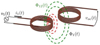 |
Fig. 1 Coupled emitting coil and receiving coil. |
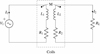 |
Fig. 2 Equivalent circuit of IPT. |
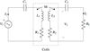 |
Fig. 3 Equivalent circuit of IPT with series-series compensation capacitors. |
 |
Fig. 4 An example of the circular coupler. |
2.1 Fundamental equations
The governing equations of the electromagnetic phenomena related to an IPT system are a subset of Maxwell's equations in the magneto dynamic case. The displacement current appearing in the right-hand side of Ampère's law is omitted since in the frequency range of inductive power systems (kHz), this term is negligible. The basic equations are:
 (1)
(1)
 (2)
(2)
with the behavior law
 (3)
(3)
where  is the magnetic field [A/m];
  the current density [A/m2];
  is the magnetic induction (or magnetic flux density) [T]; μ is the magnetic permeability [H/m].
To solve the electromagnetic problem with appropriate modeling techniques, the magnetic vector potential  can be introduced:
 (4)
(4)
where  is the magnetic vector potential [V . s/m].
The final partial differential equation to solve is then:
 (5)
(5)
The current density can be expressed with a source current density prescribed by the power supply ( ) and an induced current density in conducting materials due to eddy currents (
 . The governing equation is then expressed in the harmonic regime as:
 (6)
(6)
Using the definitions given in [15], the coupling coefficient k is defined as the ratio of the mutual inductance M (between the transmitter and the receiver) and the geometric mean of the two self-inductances L1 and L2:
 (7)
(7)
The transmitter and the receiver coil quality factors are defined as:
 (8)
(8)
where i = 1, 2 stands for the transmitter and the receiver respectively, and ω represents the angular frequency.
Moreover, the system quality factor Q is defined as the geometric mean of the two coil quality factors Q1 and Q2:
 (9)
(9)
Using the definition above, and considering the compensation configuration of Figure 3, it can be shown that the maximum efficiency of the IPT system is expressed as:
 (10)
(10)
2.2 Design considerations and computational challenges
Several coil shapes of the magnetic coupler have been proposed and evaluated in the literature so far because the geometry and configuration of the coils are crucial for determining the transmission efficiency of the resonant inductive power transfer (RIPT) system and its magnetic flux density leakage.
To solve the corresponding electromagnetic problem, equivalent circuit models or approximate analytical solutions of the electromagnetic fields are available but very limited [17–20]. For more complex geometries, numerical methods are strongly required.
Furthermore, the design of a RIPT system must be compliant with international standards to reduce the electromagnetic field (EMF) leakage to allowable levels. A shielding structure is usually placed above the receiver to minimize the leakage flux around the system, thus improving the coupling performance and leading to better efficiency and quality factor [21,22]. Different types of shielding have been reported in the literature: passive (magnetic, conductive, or both) [23–25], active [26,27], and reactive resonant [28–30]. The eddy currents produced in the shield panels (copper or aluminum) generate a magnetic field which is opposite to the field produced by the transmitter coil. As a consequence, the total magnetic field is reduced and then the performance is degraded due to the power losses in the conductive shield.
When the magnetic coupler design and compensation topology are selected, the optimization of the design for IPT systems is an active area of current research. The optimal design of magnetic coupling devices, with adequate shapes and materials, and taking into account both the efficiency of the system and the maximum level of human electromagnetic exposure, remains an open problem. There are three engineering design methodologies to select the optimal design: 1/Parameter optimization allowing a parametric sweep on geometry dimensions or material properties, 2/Shape optimization allowing the deformation the boundaries of the geometry, 3/Topology optimization allowing the determination whether a certain region of the geometry is void or solid. During the development and optimization of a RIPT system, accurate 3D models are needed, able to correctly describe the geometry, the materials (e.g., coils, ferrites, and surrounding environment), and the electromagnetic phenomena involved at the operating frequency (between 10 and 100 kHz). However, the computational cost of 3D models based on volumetric meshes (finite element method (FEM), finite difference method, etc.) is rather high. This is the reason why surrogate models and metamodeling techniques can be developed to describe the relationship between the input variables and the observed outputs.
3 High power systems (electric vehicle)
Figure 5 shows the block diagram of an IPT system for an electric vehicle. The system consists of a transmitter, a receiver, converters, and compensation networks for the transmitter and the receiver. The electrical network provides a voltage through the AC/DC converter. The magnetic field produced by the transmitter induces an alternating magnetic field in the receiver. The converters then rectify the AC power to charge the battery.
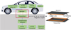 |
Fig. 5 Block diagram of an IPT system. |
3.1 Magnetic coupler
For electric vehicles, several coil shapes of the magnetic coupler have been proposed and evaluated in the literature so far because the geometry and configuration of the coils are crucial for determining the transmission efficiency of the IPT system and its magnetic flux density leakage. In Figures 6a–6c are widely used today due to their simplicity. However, other complex geometries (d), (e) and (f) have been proposed with the goal of offering a lower sensitivity to coil misalignment [31–33]. Double-D (DD) coils are composed of two equal D-shaped (rectangular) sub-coils with a shared side [34]. Based on the DD coils, the DD quadrature (DDQ) coil is implemented. It has two independent windings: one is a DD pair of coils, and another is the quadrature or quad (Q) coil. The Q-coil is placed over half of the area of each D coil [34]. Bipolar coils are similar to DD coils, but one of the coils overlaps half of the area of the D-shaped coil [35]. In order to further improve misalignment tolerance and transmission efficiency, many researchers also designed other multiple coils, such as tri-polar coils [36,37], multi-transmitters single-receiver [38], dual-transmitters dual-receivers [39], and so on. Some references [32,33] compared most of the coil structures on several factors (including coil shape, misalignment, system complexity, interoperability, and flux leakage).
Depending on national standards, the operating frequency typically ranges from 20 kHz to 100 kHz. The coupling between the two inductors takes place through an air gap, usually about 10-25 cm. Ferrites are generally added to the coils, to increase the mutual inductance, minimize leakage inductance, and also work as the magnetic shielding to decrease the magnetic flux density leakage. It has high relative permeability (µr > 1000) and a relatively low eddy current loss. There are several basic shapes of ferrite. Bar ferrite tiles are commonly used in DD, DDQ and bipolar coils, However, because of their high cost, fragility, heavy weight, and sensitivity to misalignment, many researchers proposed plate-shaped structures, which are lighter and easier to manufacture. In the context of high power, the ferrite-based IPT system may face core saturation caused by low saturation magnetic density, increased magnetic field leakage from low magnetic permeability and insufficient power density due to mechanical limitations. Fe-based nanocrystalline are now considered to be the most promising alternative to ferrite due to its flexible mechanical properties and superior magnetic properties. Nanocrystalline pads can be directly used in IPT systems [40]. The higher permeability of nanocrystalline improves the coupling performance of the magnetic coupler. To solve high eddy current loss caused by nanocrystalline pads, the structure of the core can be optimized [41].
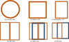 |
Fig. 6 Coil geometries. |
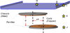 |
Fig. 7 3D structure with shielding, chassis and measurement positions (stars) for the magnetic field measures. |
3.2 Electromagnetic analysis and computational aspects
As described above, the surrounding environment in case of IPT for EVs involves: Coils, ferrite material, shielding and car. To illustrate the electromagnetic modeling part, the IPT system studied in [42] is considered. The tested EV is a KANGOO manufactured by Renault. The 3D structure of the coupling system is depicted in Figure 7. It consists of a transmitter coil, a receiver coil and two ferrite plates that completely cover the coils. A steel plate which describes a simplified model of the EV chassis is added to the design. The presence of the chassis has a significant effect on the values of the inductances. It ensures better protection for the embedded electronic devices and reduces passengers exposure to magnetic field.
Considering the range of frequency of WPT for electric vehicles (below 100 kHz), the electromagnetic problem is solved in the frequency domain using the magneto-dynamic vector potential formulation (Eq. (6)) and COMSOL software [43]. The values of self-inductances, and mutual inductance can be then calculated from magnetic energy using integration over the volume. −The chassis is made of a 5 mm-thick stainless steel (μr = 1000, σ = 106 S/m) sheet. The skin depth is very thin (∼100 µm) at 30 kHz. So, the element size in the finite element mesh should be less than 1/3 of the skin depth to have correct numerical results.
To simplify the modeling of the chassis by the finite element method (FEM), two other cases can be considered. The chassis can be considered as a perfect electric conductor. Therefore, only the mesh of the outer surface of the chassis is considered. The second-order Artificial Material Single Layer Method (AMSL_2nd order) is a powerful technique that only requires meshing the thin plate with one layer of finite elements [44]. The comparison between the different approaches shows a negligible impact occurs on the values of the inductances and to alleviate the computational burden, the AMSL can be recommended. Figure 8 shows a typical result from FEM COMSOL computation without misalignment.
The calculation of the values of L1, L2, M includes the influences of variations of the parameters: d (distance between coils) and sh (shift between the axes of the coils). Figure 9 shows the influence of d (m) variations at axial shift 0 and 0.1 m. The variations in the self-inductances L1 and L2 are large with a small air gap d, and they are small for large air gaps. This is because the ferrites and the chassis highly contribute to the magnetic flux distribution in the coupler for small air gaps. The mutual inductance M always decreases by increasing the air gap due to the increase of the leakage magnetic flux and so the coupling factor k drops. Since the chassis is conductive, induced eddy currents decrease the field radiated by the transmitter and then reduce the coupling and the mutual inductance. Additional losses due to these eddy currents decrease global efficiency. Because of the presence of chassis, the magnetic coupler is not symmetrical, and so L1 ≠ L2 in general.
It can also be noticed that L1 and L2 do not have the same variations with respect to d and sh. Without chassis these two inductances have the same value, this value varies with the position changes. The presence of the chassis leads to unsymmetrical magnetic field distributions for L1 and L2, and so, their inductances are different. The two values of these inductances vary independently with the position changes. As an experimental validation for the developed model, a 2 kW power transfer for charging a 300 V battery for the system was carried out to check the levels of magnetic field at several points in the vehicle and the nearby environment (points H, D, I, J and K in Fig. 6).
Due to the high level of magnetic stray field around high-power electromagnetic systems, the human exposure needs to be properly assessed in order to check the compliance with international standards and guidelines. Such analyses are usually made in two steps: first a proper map of the magnetic field in the vicinity area is computed, where, in a second time a human model is used to compute induced dosimetry quantities [45]. To prevent adverse consequences, several organizations have documented and issued some guidelines to regulate the usage of IPT systems. The International Commission on Non-ionizing Radiation Protection (ICNIRP) declares the recommendations for restricting field radiation and the limits to human body exposure. The version of ICNIRP 2020 guidelines covers a frequency range between 100 kHz to 300 GHz [46]. However, the IEEE C95.1-2005 [47] also offer safety levels with respect to human exposure to electric, magnetic, and electromagnetic fields from 0 Hz to 300 GHz. The SAE J2954 standard [48] defines three physical regions to facilitate EMF safety management of the RIPT system (Fig. 10). Region 1 is the entire area underneath the vehicle, including and surrounding the wireless power assemblies, which shall not extend beyond lower body structure edges. Region 2 is the region outside the periphery of vehicles. The boundary between regions 1 and 2 extends downward from the lower periphery of the vehicle body. When the vehicle is not covering the transmitter, Region 2 includes the entire area over and around the transmitter. Region 3 is the vehicle interior. It is obvious that Regions 2 and 3 must adhere to the EMF safety management principles. So, considering the restrictions on field exposure, it is necessary to estimate the magnetic flux density leakage: above the coupler and at the side of the coupler.
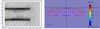 |
Fig. 8 Finite element mesh of a typical circular inductive power (axisymmetric plane) (left) and computed magnetic flux density vectors (entire view) (right). |
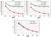 |
Fig. 9 Values of L1, L2, M and k due to variation of air gap d(m) for sh = 0 and 0.1 m. |
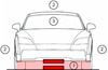 |
Fig. 10 SAE J2954 EMF regions in an EV with the RIPT system. |
4 Unmanned aerial vehicle (mid-power)
As described in the previous section, IPT systems for Electric Vehicles (EVs) are now widely studied to optimize the magnetic coupler, coil shapes, etc. In recent research, IPT technology was also adapted to unmanned aerial vehicles (UAVs). For example, a magnetic coupler with vertical spiral coils and adapted ferrite cores was introduced in [49] to improve magnetic coupling, leading to an efficiency of 90%. Other papers studied IPT systems with multiple receiver coils and aimed for a compact receiving system [50]. The results showed 84% efficiency with a 43 mm misalignment tolerance. In the same concept, authors in [51] focused on designing a pad capable of charging multiple drones at the same time. The research resulted in 86% efficiency with 4 receiver coils. A reverse methodology was proposed in [52] with multiple transmitters to maintain high efficiency levels against misalignment. In [53], authors proposed a receiver coil with a customized shape for a UAV's chassis. However, despite several published contributions, the design of an effective WPT system remains an important challenge.
4.1 Magnetic coupler
To illustrate, the IPT system presented in this section is designed to be fitted to a DJI F450 UAV model (Fig. 11), which operates without additional landing gear (Tab. 1). One advantage of this UAV configuration is the proximity of the coils, which improves coupling efficiency. The configuration of the WPT system is illustrated in Figure 12. The primary part and the secondary part are associated with compensation networks in the same way as for electric vehicles (EVs). A ferrite plate is placed directly on top of the secondary coil to reinforce the coupling between the two coils and serve as a shielding material for the onboard electronics.
One of the main challenges of IPT for UAVs is to ensure accurate landing, as this aspect depends directly on the precision of the UAV's GPS. Inaccurate positioning can cause misalignment between the transmitting coil and the receiver coil, leading to weak power transfer. To mitigate this issue, the size of the transmitter coil is chosen to be twice that of the receiver coil, providing a larger effective area for WPT despite potential misalignment. For this reason, coils are chosen to be planar circular. An operating frequency of 150 kHz is adopted for this type of IPT, commonly used for medium-power applications (from 50 to 100 W).
Figure 13 shows the model of the coupler where each coil is modeled as a flat crown to replace the parallel circular turns of a flat coil characterized by an outer radius, several turns, and a wire diameter (Tab. 2). The coils are constructed using Litz wire, which reduces the skin effect. The Litz wire used is made up of 1020 strands, each with a diameter of 0.05 mm, for a total wire diameter Dfil of 2.55 mm, including the insulation layer. The effective conductor cross-sectional area (excluding insulation) is calculated based on Litz wire data, and is then used to deduce the effective wire diameter Dsp=1.6 mm. A homogeneous current density is then prescribed in the FEM model. When the coils are aligned, a 2D axisymmetric electromagnetic analysis is sufficient. In case of misalignment (Fig. 14), a 3D modeling approach is required.
Figure 15a displays the variations of self-inductances and mutual inductances versus misalignment distance. The maximal efficiency (6) is plotted in Figure 15b. All computed results have been validated against experimental results [54]. The FEM and experimental results show almost identical trends with less than 10% error. The primary self-inductance L1 remains relatively constant despite misalignment with a slight increase beyond 50 mm due to the relative displacement of the ferrite above the receiver coil. Since the two coils are positioned closely together (10 mm apart), the ferrite above the receiver coil has an influence on the primary inductance. The secondary self-inductance L2 remains unchanged versus misalignment. With the receiver coil fixed below the ferrite, the ferrite exerts a constant impact on the L2 as misalignment changes. A progressive increase of the mutual inductance M is observed up to a misalignment of 50 mm, which is followed by a decrease beyond this point. This curve indicates that maximum coupling between the two coils occurs when their axes are misaligned by approximately 50 mm. This can be explained by the size difference between the coils. The receiver coil, being half the size of the transmitter coil, can capture a higher magnetic field density from the transmitter coil when they are misaligned compared to when they are perfectly aligned.
In order to increase the magnetic coupling, a square ferrite plate (side 100 mm; thickness 2 mm, µr = 2500) is added to the coils (Fig. 16). The 3D FEM model only involves the bottom base of the UAV since it contains a printed circuit board (PCB) frame (Fig. 17). The other parts of the UAV are removed to reduce the complexity of the 3D model because they are made of non-conductive materials and have no significant impact on the magnetic field behavior. Figure 18 shows the maximum efficiency for the complete structure (IPT system on board). The results are compared to those obtained without the bottom base (IPT system off board) with and without the ferrite plate. Clearly, the surrounding environment of the coils has a significant impact on the performance; it demonstrates that a realistic design requires detailed numerical analysis. In this configuration, no approximate analytical solution cannot be developed.
 |
Fig. 11 Studied drone. |
 |
Fig. 12 Position of the IPT system. |
Technical specifications.
 |
Fig. 13 Coils configurations and cross-section without misalignment. |
 |
Fig. 14 Coils configurations in case of misalignment. |
Parameters of the coupler.
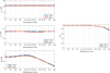 |
Fig. 15 Results for the IPT with coils only. a) Inductances versus misalignment. b) Maximal efficiency versus misalignment. |
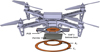 |
Fig. 16 Detailed IPT system with coils and ferrite plate. |
 |
Fig. 17 Detailed of modeled IPT system. |
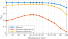 |
Fig. 18 Maximum efficiency versus misalignment. |
5 Biomedical implant (low power)
Implantable Medical Devices (IMDs) exhibit diverse implementation scenarios, encompassing life support (e.g., pacemakers), health condition monitoring (e.g., pill cameras), daily living assistance (e.g., cochlear implants, nerve stimulators), and even pain management (e.g., spinal cord stimulators) [14]. In traditional IMDs—with pacemakers being the most well-known example—batteries have long served as the sole power source. Owing to the mature development of battery technology, this power supply approach can ensure a stable and reliable energy output; however, it suffers from two critical limitations: first, batteries occupy a substantial volume relative to the IMD itself, and second, they require replacement each time their charge is depleted. Notably, the power consumption of IMDs is typically low, ranging from several microwatts [55] to several milliwatts [56]. This low-power characteristic lays the foundation for the practical application of wireless power transfer (WPT) technology in powering IMDs.
In recent years, a variety of WPT-based methods have been verified to be effective for powering IMDs, as depicted in Figure 19.
Among these wireless powering methods, resonant inductive coupling and strongly coupled magnetic resonance (SCMR) represent the most widely adopted techniques for IMD applications. As reported in [57], for a given implantation depth and transmission distance, SCMR systems exhibit higher efficiency and improved safety compared to resonant coupling systems when delivering the same amount of power. Consequently, the following sections provide a detailed description and analysis of the SCMR method, including its feasible design process and key considerations.
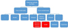 |
Fig. 19 Existing WPT-based methods for IMDs. |
5.1 General structure
A typical SCMR system comprises a source loop, a transmit resonator (Tx), a receive resonator (Rx), and a load loop, as illustrated in Figure 20. To achieve maximum power transfer efficiency (PTE), the two resonators (Tx and Rx) are designed to operate at the same resonant frequency band [58]. In contrast to traditional inductive coupling methods, the SCMR approach enables a longer transmission distance with an equivalent-sized transmission structure. In biomedical application scenarios, the SCMR system is often modified into a conformal SCMR (CSCMR) system. In this modified configuration, the receive resonator (Rx) and the load loop are arranged in a co-planar layout—this design prioritizes miniaturization and maximizes the mutual magnetic flux captured by the load loop from the resonator, at the cost of a slight reduction in transmission distance.
Resonators are typically constructed using an LC circuit, which consists of an inductive coil (L) and a capacitor (C). However, certain specialized structures—such as bifilar spirals—can also form a resonant LC circuit by utilizing the parasitic capacitance inherent in the coil's helical architecture as the circuit's capacitor [59]. In the design process, resonators are usually engineered to have a high-quality factor (Q) to maximize transmission efficiency. Nevertheless, a high Q value corresponds to a narrow resonant frequency bandwidth; if any frequency shift occurs, this narrow bandwidth can lead to a significant reduction in power transfer efficiency (PTE). Such frequency shifts may be induced by changes in the permittivity of surrounding tissues (which can occur during physiological activities) or variations in the coupling coefficient with other devices. Thus, achieving a balance between Q value and bandwidth is critical for the design of SCMR resonators.
To achieve this balance between the quality factor (Q) and bandwidth, in addition to reducing the Q factor, a superstrate is typically deposited on the metallic surface of the resonator. This superstrate stabilizes the permittivity of the surrounding environment, thereby reducing potential frequency shifts and ensuring sustained high power transfer efficiency (PTE).
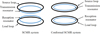 |
Fig. 20 Common structures for SCMR and CSCMR systems. |
5.2 General size and implantation environment
The size of SCMR resonators must be compatible with the IMDs power; among common IMDs, implantable cardioverter-defibrillators (ICDs) are typically the largest. For instance, Medtronic's Cobalt™ MRI SureScan™ ICD has dimensions of 66 × 51 × 13 mm3 [60]. Such ICDs are generally implanted shallowly beneath the clavicle, on the surface of the pectoralis major muscle, with an implantation depth ≤1 cm. Another representative IMD is the leadless pacemaker: Medtronic's Micra™ leadless pacemaker features a cylindrical design with an estimated diameter of 26.7 mm and height of 6.7 mm (derived from its published volume). This device is implanted within the heart's ventricle, with an estimated implantation depth of approximately 10 cm.
Commonly used implantation environment models for SCMR system analysis are categorized into three types: single-layer models, multi-layer simplified models, and realistic human models. Each model is tailored to specific application scenarios, as detailed below:
Single-layer model: This is the simplest of the three, typically consisting of a cuboid of a single human tissue type (e.g., skin or muscle), as shown in Figure 21a. It is primarily used for shallow implantation scenarios (≈1 cm) or preliminary feasibility studies. While this model sacrifices some accuracy, it significantly reduces computational time.
Multi-layer simplified model: Evolved from the single-layer model, this configuration accounts for permittivity differences between distinct tissue types without introducing excessive complexity. It is suitable for deeper implantation scenarios, where multiple tissue layers lie along the power transmission path. By adjusting the number, shape, and type of tissue layers, this model can accommodate most application scenarios; the most frequently included tissues are skin, muscle, fat, and bone, owing to their substantial permittivity disparities. For organ-specific implants (e.g., cardiac devices), the target organ and all intervening tissues along the transmission path must be incorporated into the model.
Realistic human model: This model most closely approximates the anatomical structure and tissue properties of a real human body. Despite its high accuracy, it requires extensive computational time—even for a single simulation. Consequently, it is typically reserved for the final validation step before prototype fabrication and in-vitro/in-vivo measurements.
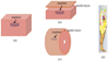 |
Fig. 21 (a) Single-layer model, (b) Multi-layer cubic model (torso), (c) Multi-layer cylindrical model (limbs) and (d) Realistic human model (Hugo) in CST [61]. |
5.3 Frequency
In biomedical applications, higher frequency bands (in the megahertz, MHz, range) are employed to facilitate the miniaturization of implanted devices. Typically, the following Industrial, Scientific, and Medical (ISM) bands are utilized for this purpose: 6.765–6.795 MHz, 13.553–13.567 MHz, 26.957–27.283 MHz, 40.66–40.70 MHz and 83.996–84.004 MHz. At higher frequency bands, the inductive loop may exhibit self-resonant behavior; beyond this resonant frequency, the loop's impedance characteristic may shift from inductive to capacitive. It is noteworthy that certain electronic components are possible to exhibit resonant frequencies near these ISM bands; in such cases, the electronic properties of these components could undergo undesirable changes.
5.4 Safety issues
Safety remains a primary concern extensively addressed by researchers in the field of wirelessly powered IMDs. The Specific Absorption Rate (SAR)—a key metric quantifying the power absorbed by human tissue—is formally defined as:

where ρ is the mass density of the tissue (kg/m3), and E is the electric field strength in the tissue sample (V/m) and σ is the conductivity of the tissue (S/m).
Safety standards for wireless power transfer systems vary with the operating frequency band. As discussed in the “Frequency Selection” section, inductive coupling-based systems for biomedical implants typically operate within the range of several megahertz to several tens of megahertz. For this frequency range, safety constraints are imposed on three critical parameters: electromagnetic field strength, power density, and SAR value. Table 3 summarizes the relevant IEEE safety standards for systems operating from 3 MHz to 100 MHz.
6 Metamodeling and multi-objective optimization
A 3D computational approach gives reliable results about the electrical parameters (mutual inductance, transmission efficiency) and the magnetic parameters (magnetic flux density leakage) of the system, but it may lead to heavy computations that have to be repeated for each new configuration that are highly dependent on various parameters: the size of coils, geometrical characteristics of the system (e.g., ferrite plates, shielding plates), possible misalignment between transmitter and receiver while charging. The introduction of meta-modeling techniques (surrogate models) enables the management of the variability of design parameters describing the electromagnetic problem and to quantitatively determine the contribution of each design variable to the observed output [64]. Several meta-modeling techniques have been developed in the literature to describe the relationship between the input variables and the observed output, such as Support Vector Regression (SVR), Multigene Genetic Programming Algorithm (MGPA), and Polynomial Chaos Expansions (PCE) [65].
To illustrate the potential of the approach, an electric vehicle charging station has been modeled in the framework of the MICEV project that includes the car-body of a Volvo S80 sedan car (kindly provided by Volvo Cars [66]) with the IPT system positioned centrally (see Fig. 22). The system has been limited to the car chassis and the charging pad, while this IPT system has a rated power up to 7.5 kW and a resonance frequency of 85 kHz. The distance between the coils was 150 mm. The metal thickness of the chassis is assumed to be 1 mm. The following three input parameters have been considered to perform sensitivity analysis: Conductivity of the chassis (σ); Relative permeability of the chassis (μr); Relative permeability of the ferrite in the charging pad (μf). The output is the amplitude of the magnetic flux density evaluated along a vertical line (101 points) which embodies a bystander position. Different meta-models have been computed corresponding to different sets of data points in order to produce an accurate and consistent meta-model able to predict the radiated fields at low cost [66]. Four metamodels used existing precomputing data regarding the variation of 3 input parameters (σ = 5*106 S/m; μr = 200; μf = 2000). A metamodel calculated with the full set of 24 datapoints, then three metamodels calculated by randomly taking 18, 12 and 6 datapoints out of the full set. The goal was to observe if initially computing less than 24 points would still produce an accurate metamodel on the given domain. Figure 23 shows a comparison between the results obtained by the 18 datapoints meta-model and those computed by the original full-wave FEM model. It can be clearly observed that the meta-model can perfectly interpolate the input model to produce an estimate accurate enough to perform sensitivity analysis that could help design an IPT system compliant with the safety guidelines.
Such meta-models could obviously be used in various applications and other fields. In [67], the approach allowed performing a sensitivity analysis of a wireless power transfer link involving biomedical implants in the surrounding biological environment. The impact of geometrical parameters of the implant and physical properties of the biological tissue was evaluated efficiently at low computational cost thanks to a meta-model based on the polynomial chaos expansion.
The optimization of IPT systems is an active research topic. Three approaches are available:
Parameter optimization allows a parametric sweep on geometric dimensions or material properties, such as the ferrite length and width, coil wire position, number of coil turns, separation between turns, size and position of ferrites, etc.
Shape optimization allows deforming the boundaries of the geometry, such as the coil shape, the ferrite shape, or the shielding shape.
Topology optimization allows determine whether a certain region of the geometry is void or solid, for example, how to arrange the ferrite structure under the transmitter or above the receiver.
In [65] a fast and efficient modeling methodology to assess the efficiency of RIPT systems was proposed to manage electromagnetic compatibility (EMC) constraints in EVs. Combining meta-models with parametric optimization allows performing a fast multi-objective optimization considering both the performance of the system (including ferrite and shielding structures) and the cost. However, the optimization procedure, based on evolutionary algorithms does not allow the modification of the topology of the structure and the shape of ferrite structures (rectangular or circular) and limits the possible shapes. The advantage of topology optimization is to modify the initial shape of the ferrite plates and to introduce holes in the plates. Such optimization allows to decrease the weight of the ferrite material (and the major cost) while providing better performances of the magnetic coupler. The solid isotropic material with penalization (SIMP) method, which is today the most used due to its easy and intuitive implementation, is adopted to arrange the ferrite distribution [68]. The SIMP method discretizes a studied domain into numerous elements, for which artificial density values are introduced as design variables. The material properties between the solid and void are interpolated with a smooth continuous function, which depends on the material density. Then, as it is desired here to optimize the topology of the ferromagnetic materials, the adequate choice is to consider only permeability as the material property. The optimization process leads to the removal of the ferrite from the center and the edges of the ferrite plates, regardless of the constraint of the ferrite volume ratio (Figs. 24 and 25). Arranging the ferrite plates with this algorithm can achieve a 40% reduction of the ferrite volume and reduce the ferrite core loss of 5%. Additionally, it maintains approximately the initial performance with around 10% reduction in the mutual inductance. This optimization procedure can also be applied in case of a conductive shielding above the magnetic coupler. It is shown that the shield has a clear impact on the ferrite arrangement at the receiver side.
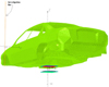 |
Fig. 22 3D FEM model mesh of the chassis investigation line. |
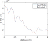 |
Fig. 23 B-field obtained from the surrogate (estimated) against the one with the original model. |
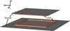 |
Fig. 24 Initial ferrite volume. |
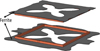 |
Fig. 25 Coupler with 40% reduction of the ferrite volume. |
7 Conclusion
This paper has provided an overview of inductive power transfer systems with an emphasis on 3D full-wave modeling approach for the magnetic coupler and its surrounding environment. Basic first principles were presented, and three illustrative examples were detailed covering a wide range of transferred power (from mW to kW): electric vehicles, UAVs and biomedical implants. Major steps of a 3D modeling technique were presented and similarities between these different applications were highlighted. These examples are sufficiently practical to show how real-world IPT systems can be efficiently designed and optimized with the described methods that are available in the engineering community. For each section of the paper, some reference works were cited allowing the reader to gain an overview about the state of the art and pursue in-depth studies if required. It is expected that the paper serves as an introductory resource for newcomers to this topic and encourages young researchers to investigate this stimulating research area.
Acknowledgments
This paper presents the know-how and experience of the authors in inductive power transfer while developing several research and industry projects in their own institutions. The authors are grateful to many colleagues and especially PhD students who have been involved during different research activities.
Funding
This research received a partial funding of a 2025 “Haiju project” supported by Sichuan Science and Technology Program of the People's Republic of China.
Conflicts of interest
The authors have nothing to disclose.
Data availability statement
This article has no associated data generated and/or analyzed.
Author contribution statement
This research was collaboratively developed and reviewed by the authors: Shuoliang Ding (S.D), Lionel Pichon (L.P.) and Yifan Chen (Y.C.). Conceptualization, S.D. and L.P.; Methodology, S.D. and L.P.; Formal Analysis, S.D. and L.P.; Investigation, S.D. and L.P.; Writing–Original Draft Preparation, S.D. and L.P.; Writing–Review & Editing, S.D. and L.P.; Supervision, L.P. and Y.C. Project administration, L.P. and Y.C.

Shuoliang Ding was born in Shenyang, China, in 1994. He received the Diploma Engineer degree from the Ecole Centrale de Nantes in France and the Diploma master's degree from Beihang University, Beijing, China in 2017. He received then the Ph.D. degree from University of Paris-Saclay, Paris France. During his Ph.D. study, he has authored several papers in international conferences. He is now persuing a post-doctoral project at the Yangtze Delta Region Institute of University of Electronic Science and Technology of China. His current research interests include bio-electromagnetics, antenna theory, implantable sensing, and implantable powering for biomedical applications.

Lionel Pichon is Senior Researcher (Directeur de recherche) at the CNRS (French National Centre for Scientific Research) in GeePs (Group of electrical engineering of Paris). His research interests include computational electromagnetics, electromagnetic compatibility and wireless power transfer. He received the Dip. Eng. from ESIEE-Paris (Ecole Supérieure d'Ingénieurs en Electronique et Electrotechnique) in 1984. In 1985 he joined the Laboratoire de Génie Electrique de Paris (LGEP, now GeePs) where he earned a PhD in electrical engineering in 1989. He got a position at the CNRS in 1989.

Yifan Chen (Senior Member, IEEE) received the B.Eng. (Hons. I) and Ph.D. degrees in electrical and electronic engineering from Nanyang Technological University, Singapore. He is a Distinguished Professor with the School of Life Science and Technology, University of Electronic Science and Technology of China, Chengdu, China. He has held various academic and leadership positions in top-tier universities in China, New Zealand, U.K., and Singapore. His current research interests include in vivo computation where computing meets bio-sensing, molecular and biological communications where communicating meets bio-transporting, and electromagnetic biomedicine where radio frequency sensing meets bio-imaging.
References
- C.T. Rim, C. Mi, in Wireless Power Transfer for Electric Vehicles and Mobile Devices (John Wiley & Sons, Ltd, New York, 2017) [Google Scholar]
- M. Feliziani, T. Campi, S. Cruciani, F. Maradei, in Wireless Power Transfer for E-Mobility: Fundamentals and Design Guidelines for Wireless Charging of Electric Vehicles (Academic Press, Cambridge, Massachusetts, 2023). https://doi.org/10.1016/C2021-0-01579-0 [Google Scholar]
- L. Pichon, Electromagnetic analysis and simulation aspects of wireless power transfer in the domain of inductive power transmission technology, J. Electromagn. Waves Appl. 34, 1719 (2020), https://doi.org/10.1080/09205071.2020.1799870 [Google Scholar]
- S. Ghazizadeh, S. Mekhilef, M. Seyedmahmoudian, J. Chandran, A. Performance evaluation of coil design in inductive power transfer for electric vehicles, IEEE Access, 12, 108201 (2024), https://doi.org/10.1109/ACCESS.2024.3439027 [Google Scholar]
- M.M. Rahman, M.S.I. Shanto, N. Sarker, T. Rani, L.C. Paul, A comprehensive review of wireless power transfer methods, applications, and challenges, Eng. Rep. 6, e12951 (2024), https://doi.org/10.1002/eng2.12951 [Google Scholar]
- M. Rehman et al., A review of inductive power transfer: emphasis on performance parameters, compensation topologies and coil design aspects, IEEE Access, 11, 144978 (2023), https://doi.org/10.1109/ACCESS.2023.3344041 [Google Scholar]
- A. Jawad, H. Jawad, R. Nordin, S. Gharghan, N. Abdullah, M. Abu Al-Shaeer, Wireless power transfer with magnetic resonator coupling and sleep/active strategy for a drone charging station in smart agriculture, IEEE Access 7, 139839 (2019) [Google Scholar]
- S. Duan, X. Lu, H. Wu, H. Zhang, Z. Zhang, G. Wang, Unmanned aerial vehicle wireless power transfer system for long distance transmission line patrol, in: Proceedings of the IEEE International Power Electronics and Application Conference and Exposition (PEAC), (Guangzhou, China, 4–7 November 2022), pp. 1324–1329 [Google Scholar]
- L. Moraes, L. Carmo, R. Campos, M.A. da Silva Junior, L. Moreira, J. Carvalho de Souza, A. Texeira, D. Silveira, T. Coelho, A. Luis et al., Autonomous quadrotor for accurate positioning, IEEE Aerosp. Electron. Syst. Mag. 32, 58 (2017) [Google Scholar]
- C. Rong et al., Critical review of recent development of wireless power transfer technology for unmanned aerial vehicles, IEEE Access 11, 132982 (2023), https://doi.org/10.1109/ACCESS.2023. 3332470 [Google Scholar]
- X. Mou, D. Gladwin, J. Jiang et al., Near-field wireless power transfer technology for unmanned aerial vehicles: a systematical review, IEEE J. Emerg. Sel. Top. Ind. Electron. 4, 147 (2023) [Google Scholar]
- U. Gordhan, S. Jayalath, Comparative analysis of wireless power transfer couplers for unmanned aerial vehicles and drones, IEEE Open J. Power Electron. 5, 618 (2024), https://doi.org/10.1109/OJPEL.2024.3395174 [Google Scholar]
- P. Pérez-Nicoli, F. Silveira, M. Ghovanloo, Inductive Links for Wireless Power Transfer (Springer International Publishing, 2021) [Google Scholar]
- S. Ding, S. Koulouridis, L. Pichon, Implantable wireless transmission rectenna system for biomedical wireless applications, IEEE Access, 8, 195551 (2020) [Google Scholar]
- R.W. Erickson, D. Maksimović, Inductor design, in Fundamentals of Power Electronics, edited by R.W. Erickson, D. Maksimović (Springer US, Boston, MA, 2001), pp. 539–564. https://doi.org/10.1007/0-306-48048-4_14 [Google Scholar]
- M. Budhia, G.A. Covic, J.T. Boys, Design and optimization of circular magnetic structures for lumped inductive power transfer systems, IEEE Trans. Power Electron. 26, 3096 (2011), https://doi.org/10.1109/TPEL.2011.2143730 [CrossRef] [Google Scholar]
- D.C. Yates, A.S. Holmes, A.J. Burdett, Optimal transmission frequency for ultralow-power short-range radio links, IEEE Trans. Circuits Syst. I: Regul. Pap. 51, 1405 (2004), https://doi.org/10.1109/TCSI.2004.830696 [Google Scholar]
- S.I. Babic, C. Akyel, New analytic-numerical solutions for the mutual inductance of two coaxial circular coils with rectangular cross section in air, IEEE Trans. Magn. 42, 1661 (2006) [Google Scholar]
- M. Parise, G. Antonini, D. Romano, On the flux linkage between pancake coils in resonance-type wireless power transfer systems, Int. J. Antennas Propag. 2020, 1 (2020) [Google Scholar]
- M. Parise, M. Quercio, A. Laudani, Efficient analytical evaluation of inductive coupling strength in wireless power transfer systems, IEEE Access 12, 143263 (2024), https://doi.org/10.1109/ACCESS.2024.3471902 [Google Scholar]
- D. Patil, M.K. McDonough, J.M. Miller, B. Fahimi, P.T. Balsara, Wireless power transfer for vehicular applications: overview and challenges, IEEE Trans. Transport. Electrific. 4, 3 (2018) [CrossRef] [Google Scholar]
- M.L. Hiles, R.G. Olsen, K.C. Holte, D.R. Jensen, K.L. Griffing, Power frequency magnetic field management using a combination of active and passive shielding technology, IEEE Trans. Power Deliv. 13, 171 (1998), https://doi.org/10.1109/61.660875 [Google Scholar]
- M. Mohammad, E.T. Wodajo, S. Choi, M.E. Elbuluk, Modeling and design of passive shield to limit EMF emission and to minimize shield loss in unipolar wireless charging system for EV, IEEE Trans. Power Electron. 34, 12235 (2019), https://doi.org/10.1109/TPEL.2019.2903788 [Google Scholar]
- T. Campi, S. Cruciani, M. Feliziani, Magnetic shielding of wireless power transfer systems, in Proc. Int. Symp. Electromagn. Compat., (Tokyo, Japan, May 2014), pp. 422–425 [Google Scholar]
- K. Kadem et al., An efficient method for dimensioning magnetic shielding for an induction electric vehicle charging system, in Progress In Electromagnetics Research (EMW Publishing, 2021), Vol. 170, pp. 153–167 [Google Scholar]
- S.Y. Choi, B.W. Gu, S.W. Lee, W.Y. Lee, J. Huh, C.T. Rim, Generalized active EMF cancel methods for wireless electric vehicles, IEEE Trans. Power Electron. 29, 5770 (2014) [Google Scholar]
- T. Campi, S. Cruciani, F. Maradei, M. Feliziani, Magnetic field mitigation by multicoil active shielding in electric vehicles equipped with wireless power charging system, IEEE Trans. Electromagn. Compat. 62, 1398 (2020) [Google Scholar]
- J. Park et al., Planar multiresonance reactive shield for reducing electromagnetic interference in portable wireless power application, Appl. Phys. Lett. 114, 203902 (2019), https://doi.org/10.1063/1.5097038 [Google Scholar]
- S. Kim, H.-H. Park, J. Kim, J. Kim, S. Ahn, Design and analysis of a resonant reactive shield for a wireless power electric vehicle, IEEE Trans. Microw. Theory Technol. 62, 1057 (2014) [Google Scholar]
- H. Moon, S. Kim, H.H. Park, S. Ahn, Design of a resonant reactive shield with double coils and a phase shifter for wireless charging of electric vehicles, IEEE Trans. Magn. 51, 1 (2015) [CrossRef] [Google Scholar]
- A. Triviño-Cabrera, J.M. González-González, J.A. Aguado, in Wireless Power Transfer for Electric Vehicles: Foundations and Design Approach (Springer Nature, Dordrecht, GX, Netherlands, 2020) [Google Scholar]
- S. Jayalath, A. Khan, Design, challenges, and trends of inductive power transfer couplers for electric vehicles: a review, IEEE J. Emerg. Sel. Topics Power Electron. 9, 6196 (2021), https://doi.org/10.1109/JESTPE.2020.3042625 [Google Scholar]
- A.A.S. Mohamed, A.A. Shaier, H. Metwally, S.I. Selem, A comprehensive overview of inductive pad in electric vehicles stationary charging, Appl. Energy 262, 114584 (2020) [Google Scholar]
- M. Budhia, J.T. Boys, G.A. Covic, C.Y. Huang, Development of a single-sided flux magnetic coupler for electric vehicle IPT charging systems, IEEE Trans. Ind. Electron. 60, 318 (2013) [CrossRef] [Google Scholar]
- A. Zaheer, G.A. Covic, D. Kacprzak, A bipolar pad in a 10-kHz 300-W distributed IPT system for AGV applications, IEEE Trans. Ind. Electron. 61, 3288 (2014) [Google Scholar]
- H. Matsumoto, Y. Neba, H. Iura, D. Tsutsumi, K. Ishizaka, R. Itoh, Trifoliate three-phase contactless power transformer in case of winding-alignment, IEEE Trans. Ind. Electron. 61, 53 (2014), https://doi.org/10.1109/TIE.2013.2242421 [Google Scholar]
- S. Kim, G.A. Covic, J.T. Boys, Tripolar pad for inductive power transfer systems for EV charging, IEEE Trans. Power Electron. 32, 5045 (2017) [CrossRef] [Google Scholar]
- Y. Li, R. Mai, L. Lu, Z. He, A novel IPT system based on dual coupled primary tracks for high power applications, J. Power Electron. 16, 111 (2016) [Google Scholar]
- Y. Li, T. Lin, R. Mai, L. Huang, Z. He, Compact double-sided decoupled coils-based WPT systems for high power applications: analysis, design, and experimental verification, IEEE Trans. Transp. Electrific. 4, 64 (2018) [Google Scholar]
- W. Zhang, S. Kim, G.A. Covic, Nanocrystalline core losses in high power IPT systems for EV charging applications, IEEE Open J. Power Electron. 6, 537 (2025), https://doi.org/10.1109/OJPEL. 2025.3553159 [Google Scholar]
- D.E. Gaona, C. Jiang, T. Long, Highly efficient 11.1-kW wireless power transfer utilizing nanocrystalline ribbon cores, IEEE Trans. Power Electron. 36, 9955 (2021) [Google Scholar]
- M. Ibrahim, L. Pichon, L. Bernard et al., Advanced modeling of a 2-kW series-series resonating inductive charger for real electric vehicle, IEEE Trans. Veh. Technol. 64, 421 (2015) [Google Scholar]
- Comsol, https://www.comsol.com/ [Google Scholar]
- S. Cruciani, T. Campi, F. Maradei, M. Feliziani, Conductive layer modeling by improved second-order artificial material single-layer method, IEEE Trans. Antenn. Propag. 66, 5646 (2018), https://doi.org/10.1109/TAP.2018.2854413 [Google Scholar]
- P. Ankarson, O. Bottauscio, B. Clarke, F. Freschi, R. Guilizzoni et al., in Best Practice Guide for the Assessment of EMF Exposure from Vehicle (Wireless Power Transfer Systems, 2021) [Google Scholar]
- ICNIRP, ICNIRP guidelines for limiting exposure to electromagnetic fields (100 kHz to 300 GHz), Health Phys. 118, 483 (2020) [Google Scholar]
- IEEE C95. 1- 2005 - IEEE Standard for Safety Levels with Respect to Human Exposure to Electric, Magnetic, and Electromagnetic Fields, 0 Hz to 300 GHz [Google Scholar]
- SAE Standard, J2954, wireless power transfer for light-duty plug-in/electric vehicles and alignment methodology, p. 2019. Accessed: Feb 9 2016 [Google Scholar]
- X. Li, J. Lu, S. Stegen, Magnetic coupler optimization for inductive power transfer system of unmanned aerial vehicles, Energies 14, 7024 (2021), https://doi.org/10.3390/en14217024 [Google Scholar]
- C. Cai, J. Wang, F. Zhang, X. Liu, P. Zhang, Y.-G. Zhou, A multichannel wireless UAV charging system with compact receivers for improving transmission stability and capacity, IEEE Syst. J. 16, 997 (2022), https://doi.org/10.1109/JSYST.2021.3085914 [Google Scholar]
- Y. Zeng, C. Lu, C. Rong, M. Liu, Optimization design of wireless charging system with uniform magnetic field for multi drone, in 2021 IEEE 2nd China International Youth Conference on Electrical Engineering (CIYCEE) (Chengdu, China, 2021), pp. 1–6, https://doi.org/10.1109/CIYCEE53554.2021.9676744 [Google Scholar]
- T. Campi, S. Cruciani, M. Feliziani, Wireless power transfer technology applied to an autonomous electric UAV with a small secondary coil, Energies 11, 352 (2018), https://doi.org/10.3390/en11020352 [CrossRef] [Google Scholar]
- S. Aldhaher, P.D. Mitcheson, J.M. Arteaga, G. Kkelis, D.C. Yates, Light-weight wireless power transfer for mid-air charging of drones, in 2017 11th European Conference on Antennas and Propagation (EUCAP) (Paris, France, 2017), pp. 336–340, https://doi.org/10.23919/EuCAP.2017.7928799 [Google Scholar]
- M. Terrah, M.-K. Smail, L. Pichon, M. Bensetti, Parametric design approach for wireless power transfer system: UAV applications, Drones 8, 735 (2024), https://doi.org/10.3390/drones8120735 [Google Scholar]
- S. Ding, S. Koulouridis, L. Pichon, Miniaturized implantable power transmission system for biomedical wireless applications, Wirel. Power Transf. 7, 1 (2020). https://doi.org/10.1017/wpt.2019.16 [Google Scholar]
- I.M. Imani, H.S. Kim, M. Lee, S.B. Kim, S.M. Song, D.G. Lee, J.H. Hwang, J. Lee, I.Y. Suh, S.W. Kim, J. Chen, H. Kang, D. Son, J.M. Baik, S. Hur, H.C. Song, A body conformal ultrasound receiver for efficient and stable wireless power transfer in deep percutaneous charging, Adv. Mater. 37, 2419264 (2025), https://doi.org/10.1002/adma.202419264 [Google Scholar]
- K.S. Nikita, Handbook of Biomedical Telemetry, 1st edn. (Wiley-IEEE Press, Hoboken, NJ, USA, 2014) [Google Scholar]
- A. Kurs et al., Wireless power transfer via strongly coupled magnetic resonances, Science 317, 83 (2007), https://doi.org/10.1126/science.1143254 [CrossRef] [PubMed] [Google Scholar]
- R. Narayanamoorthi, A.V. Juliet, Capacitor-less high-strength resonant wireless power transfer using open bifilar spiral coil, IEEE Trans. Appl. Supercond. 29, 1 (2019), https://doi.org/10.1109/TASC.2018.2848268 [Google Scholar]
- Cobalt XT DR ICD DDPA2D4 Spec Sheet, Medtronic, UC 2020 01370 EN ©2020 Medtronic. Minneapolis, MN. Printed in USA. 08/2020 [Google Scholar]
- Voxel data (Hugo), Computer Simulation Technology (CST) STUDIO SUITE. Version 2017, Dassault Systems, Simulia Corp, Johnston, RI, USA, http://www.cst.com [Google Scholar]
- IEEE, IEEE standard for safety levels with respect to human exposure to radiofrequency electromagnetic fields, 3 kHz to 300 GHz, IEEE Standard C95. 1, 2005 [Google Scholar]
- Federal Communications Commission (FCC), Human exposure to radiofrequency electromagnetic fields and reassessment of FCC radiofrequency exposure limits and policies, Fed. Regist. 85, 18131 (2020), https://www.federalregister.gov/documents/2020/04/01/2020-02745/human-exposure-to-radiofrequency-electromagnetic-fields-and-reassessment-of-fcc-radiofrequency [Google Scholar]
- S. Marelli, B. Sudret, Uqlab: A framework for uncertainty quantification in matlab, in: Vulnerability, Uncertainty, and Risk: Quantification, Mitigation, and Management (2014), pp. 2554–2563 [Google Scholar]
- Y. Pei, L. Pichon, Y. Le Bihan, M. Bensetti, P. Dessante, Fast shielding optimization of an inductive power transfer system for electric vehicles, IEEE Access 10, 91227 (2022), https://doi.org/10.1109/ACCESS.2022.3198953 [Google Scholar]
- P. Lagouanelle, O. Bottauscio, L. Pichon, M. Zucca, Impact of parameters variability on the level of human exposure due to inductive power transfer, IEEE Trans. Magn. 57, 1 (2021), https://doi.org/10.1109/TMAG.2021.3062702 [CrossRef] [Google Scholar]
- S. Ding, L. Pichon, Sensitivity analysis of an implanted antenna within surrounding biological environment, Energies 13, 996 (2020), https://doi.org/10.3390/en13040996 [Google Scholar]
- Y. Pei, L. Pichon, Y. Le Bihan, M. Bensetti, SIMP-method topology optimization of ferrite structures in inductive power transfer systems, IEEE Trans. Electromagn. Compat. 65, 1 (2023), https://doi.org/10.1109/TEMC.2023.3311632 [Google Scholar]
Cite this article as: Shuoliang Ding, Lionel Pichon, Yifan Chen, Modeling of inductive power transfer systems − a tutorial review, Eur. Phys. J. Appl. Phys. 100, 33 (2025), https://doi.org/10.1051/epjap/2025033
All Tables
All Figures
|
Fig. 1 Coupled emitting coil and receiving coil. |
| In the text | |
|
Fig. 2 Equivalent circuit of IPT. |
| In the text | |
|
Fig. 3 Equivalent circuit of IPT with series-series compensation capacitors. |
| In the text | |
|
Fig. 4 An example of the circular coupler. |
| In the text | |
|
Fig. 5 Block diagram of an IPT system. |
| In the text | |
|
Fig. 6 Coil geometries. |
| In the text | |
|
Fig. 7 3D structure with shielding, chassis and measurement positions (stars) for the magnetic field measures. |
| In the text | |
|
Fig. 8 Finite element mesh of a typical circular inductive power (axisymmetric plane) (left) and computed magnetic flux density vectors (entire view) (right). |
| In the text | |
|
Fig. 9 Values of L1, L2, M and k due to variation of air gap d(m) for sh = 0 and 0.1 m. |
| In the text | |
|
Fig. 10 SAE J2954 EMF regions in an EV with the RIPT system. |
| In the text | |
|
Fig. 11 Studied drone. |
| In the text | |
|
Fig. 12 Position of the IPT system. |
| In the text | |
|
Fig. 13 Coils configurations and cross-section without misalignment. |
| In the text | |
|
Fig. 14 Coils configurations in case of misalignment. |
| In the text | |
|
Fig. 15 Results for the IPT with coils only. a) Inductances versus misalignment. b) Maximal efficiency versus misalignment. |
| In the text | |
|
Fig. 16 Detailed IPT system with coils and ferrite plate. |
| In the text | |
|
Fig. 17 Detailed of modeled IPT system. |
| In the text | |
|
Fig. 18 Maximum efficiency versus misalignment. |
| In the text | |
|
Fig. 19 Existing WPT-based methods for IMDs. |
| In the text | |
|
Fig. 20 Common structures for SCMR and CSCMR systems. |
| In the text | |
|
Fig. 21 (a) Single-layer model, (b) Multi-layer cubic model (torso), (c) Multi-layer cylindrical model (limbs) and (d) Realistic human model (Hugo) in CST [61]. |
| In the text | |
|
Fig. 22 3D FEM model mesh of the chassis investigation line. |
| In the text | |
|
Fig. 23 B-field obtained from the surrogate (estimated) against the one with the original model. |
| In the text | |
|
Fig. 24 Initial ferrite volume. |
| In the text | |
|
Fig. 25 Coupler with 40% reduction of the ferrite volume. |
| In the text | |
Current usage metrics show cumulative count of Article Views (full-text article views including HTML views, PDF and ePub downloads, according to the available data) and Abstracts Views on Vision4Press platform.
Data correspond to usage on the plateform after 2015. The current usage metrics is available 48-96 hours after online publication and is updated daily on week days.
Initial download of the metrics may take a while.