| Issue |
Eur. Phys. J. Appl. Phys.
Volume 100, 2025
Special Issue on ‘Electromagnetic modeling: from material properties to energy systems (Numelec 2024)’, edited by Lionel Pichon and Junwu Tao
|
|
|---|---|---|
| Article Number | 4 | |
| Number of page(s) | 7 | |
| DOI | https://doi.org/10.1051/epjap/2025001 | |
| Published online | 14 February 2025 | |
https://doi.org/10.1051/epjap/2025001
Original Article
Computational study of partial discharge events in electric drives with segmented power supply
GeePs, Université Paris-Saclay, CentraleSupélec, CNRS, Laboratoire de Génie Electrique et Electronique de Paris, Gif-sur-Yvette, France
* e-mail: This email address is being protected from spambots. You need JavaScript enabled to view it.
Received:
18
October
2024
Accepted:
13
January
2025
Published online: 14 February 2025
Abstract
The transportation industry (automobile, aerospace) is undergoing a significant shift towards higher voltage supply, to increase embedded power. Increasing the voltage can lead to an increase in the occurrence of partial discharges which have a deleterious impact on the insulators, and therefore of the system lifetime. The current study investigates two electric drives architecture, namely first a combination of a conventional motor with a single inverter and, second, a multi-Three-Phase machine based on highly coupled windings and combined with dedicated sub-inverter. The latter is based on CTAF concept (Chaîne de Traction à Alimentation Fractionnée for Electric Drive based on Segmented Power Supply). This innovative power supply concept is presented in the case study section. According to the goal of this study, a 54-turns coil is developed and modelled as the equivalent circuit, while the related lumped parameters are determined by a frequency-dependent electrostatic and magnetostatic COMSOL simulation. Subsequently, a MATLAB/SIMULINK simulation of the equivalent electric circuit enables assessing the voltage potential distribution. The latter is injected as input into the COMSOL electrostatic simulation to compute the electric field. Consequently, the maximum voltage supply without breakdown is determined, for both studied cases. The comparative study concludes that, between the two case studies analyzed, the minimum among the maximum voltage supplies without breakdown is observed in the system powered with the CTAF approach.
Key words: Embedded systems / partial discharges / conventional winding / segmented power supply / lumped parameter electrical model
© N. Lanciotti et al., Published by EDP Sciences, 2025
 This is an Open Access article distributed under the terms of the Creative Commons Attribution License (https://creativecommons.org/licenses/by/4.0) which permits unrestricted use, distribution, and reproduction in any medium, provided the original work is properly cited.
1 Introduction
The aerospace industry is moving towards more electric aircraft (MEA), with the ultimate goal of achieving an all-electric aircraft (AEA) [1] for medium-haul and vertical take-off and landing aircraft. In this context, hydraulic, pneumatic, and mechanical systems would be replaced, in the aircraft architecture, by advanced electrical components [2]. This drastic increase in electric power induces a tendency to increase standard voltages to limit Joule effect losses. In the aeronautic sectors, this change towards higher voltage has significant specific consequences. Many previous studies assess the impact of high voltages. The present case investigates the possibility of partial electrical discharge occurrence, tested through numerical simulations, on a classical structure of an electric machine (with or without a supply cable) and on a highly modular power traction chain structure.
These systems are attracting increasing interest from researchers and industry due to their promising characteristics, including the ability to adjust the DC bus supply voltage, enhance the electric drives resilience, and enable service continuity by reconfiguring the power supply in the event of failure of one or more sub-windings. Predominantly, multi-three-phase structures include multi-sector windings [3], multi-three-phase windings [4] and highly coupled windings [5]. This study focuses on the third type and built upon recent advancements in the CTAF (Chaîne de Traction à Alimentation Fractionnée, or Electric Drive with Segmented Power Supply) project [6].
The low voltage MOSFETs exhibit promising performance in terms of economic efficiency, reduced losses, and improved integration capabilities. Hence, regarding winding subdivision, recent studies [7] have already demonstrated that increasing the number of voltage levels in an inverter, which reduces the voltage contribution of each level, enables the use of low-voltage MOSFET technology. On the other hand, the fundamental question of partial discharges has not yet been addressed. The main contribution of this paper is to explore the potential of segmented power supply for reducing the risk of partial discharges and resulting failures while maintaining equivalent mechanical performance of the segmented electrical drive in comparison to a standard drive. Additionally, it aims to assess the influence of the number of rows on the risk of breakdown.
Various electrical models have been proposed in the literature [8] to simulate the transient behavior of winding under steep voltage edges and to calculate inter-turn voltages. The equivalent model implemented in this study adopts a turn-by-turn discretization of the winding [9], where each turn is characterized by its own resistance, inductance, and capacitance relative to the magnetic core. Capacitive and inductive couplings between turns are also included through turn-to-turn capacitances and mutual inductances. Unlike previous studies, this work incorporates dielectric losses, both between turns and between turns and the magnetic core, into the model.
To fully characterize the behavior of the drive system, a preliminary study is carried out based on a structure resembling a transformer winding rather than that of an electrical machine. This choice is made because the geometry is fully transferable to the U-slot configuration. Furthermore, experimental measurements are being prepared using the same geometry. Indeed, regarding partial discharge detection, this kind of simplified geometry is notably more practical and manageable compared to that of a full-scale electrical machine. A finite element software permits to compute the macroscopic parameters (inductances, capacities, resistances, etc.) of the winding. These values enable to establish time simulation in an dedicated simulation software. The related result is then used back in the finite element software to determine the locations where partial discharges are most likely and the associated voltage levels. This procedure enables to carry out a comparative study of the proposed electric drive and the standard one.
In addition to this first introductory part, the article is organized as follows. Section 2 describes the case study by providing more details on the CTAF project and the physics associated with electric discharges. Section 3 introduces the global simulation process and the numerical method used to compute the voltage distribution on both the whole winding and the segmented one. Section 4 discusses the results while Section 5 presents the based-on conclusion and the related perspectives.
2 Case study
2.1 Electric discharge
Electrical discharge occurs when a seed electron accelerated by an electric field acquires an energy greater than the ionization energy of gas atoms/molecules. It finally results in an electron avalanche inducing damaging local warming. Sources of seed electrons include cosmic rays, photo-ionization, and similar mechanisms. Assuming the presence of a seed electron, the conditions leading to an electron avalanche are described by the experimental Paschen's law [10,11]. Under appropriate controlled experimental conditions, the latter gives the electric field necessary to start an electric arc as a function of pressure. Paschen's law is established for two infinite and parallel planar electrodes resulting in a homogeneous electric field. Figure 1 illustrates such a curve in the case of air: it shows the breakdown voltage as a function of the product of ambient pressure and inter-electrode distance.
Note that electrical components are technically subjected to a heterogeneous rather than homogeneous electric field, increasing the probability of low-pressure electrical discharge. Furthermore, studies have demonstrated that, depending on the components within the electric drive, the Voltage Source Inverter (VSI) imposes transients that may induce up to three times the rated voltage at certain points of the electrical machine. This detrimental impact is mainly due to impedance mismatches and subsequent reflections in the cables connecting VSI with the electric machine [12].
The combined effect of voltage increase, low pressure at altitude (aircraft case and also car going up a mountain), and overvoltage associated with the power electronics converters (i.e. VSI) underscore the interest in the numerical study presented in this article.
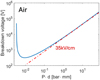 |
Fig. 1 Theoretical Paschen's curve in air. |
2.2 Electric traction chain with segmented power supply
An innovative concept, named CTAF for Chaîne de Traction à Alimentation Fractionnée (i.e. Electric Drive Chain with Segmented Power Supply in English) has been patented by the electrical engineering laboratories in Paris (SATIE and GeePs) [13]. The core idea involves dividing the power supply coils of each phase of an electrical machine into sub-coils controlled by individual power converters (VSI) with reduced power. As shown in Figure 2, one phase coil winding on a tooth, characterized by N turns, is divided in Nsc sub-coils, each one characterized by (N/Nsc) turns. As each sub-inverter uses the same electric reference potential (GND) because connected to the same DC source, this new concept holds the promise of significant quantitative advancements in overcoming the challenges previously discussed, giving a remarkable degree of flexibility in voltage sizing. The present article exclusively focuses on the CTAF ability to achieve the same magnetic flux in the electrical machine, by applying a lower voltage to each sub-coil when utilizing this novel setup. This study considers a coil division into three parts (Nsc = 3) which also leads to a division by 3 of the applied voltage. Hence, the potential of one turn is necessarily closer than (VDC/Nsc) to that of another turn.
3 Numerical method
At the beginning of the simulation process (Fig. 3), an electromagnetic simulation based on COMSOL software models a 54-turn coil representing the electromagnetic part of the standard machine. It enables to extract the lumped parameters. Subsequently, the latter are then injected into the electrical model, defined in MATLAB software, which permits to compute the temporal behavior of the entire coil (Fig. 4). Actually, the geometry studied requires a 3D modeling to fully capture the core non-axisymmetric geometry. However, a 2D axisymmetric approach can be implemented with small discrepancies. In order to do this, the dimensions of the magnetic circuit have to be modified to ensure the same magnetic flux in the ferrite cross-section. This 2D axisymmetric modeling permits to easily determine the coil parameters (as shown in Fig. 5).
Furthermore, a 50 MHz frequency is considered. It corresponds to the inverse of the 20 ns voltage rise time imposed by the VSI on the coil. Both the skin effect and the proximity effect depend on the permeability of the ferromagnetic material. Given its strong frequency dependence, the permeability value at 50 MHz is incorporated into the simulation to evaluate the coil resistance.
The CTAF simulation is performed using the same setup (Fig. 4) but divided into Nsc = 3 parts, each with 18 turns, and the three related sub-systems are connected in parallel to the voltage source, which has the same impedance as the input cable. All the values used are listed in Table 1. The dimensions and materials of the wire used are shown in Figure 6.
As shown in Table 1, the resistance and inductance values of the power cable are considered constant and calculated based on a COMSOL simulation with a 2-meters thick cable (3.55 mm diameter made of copper, PTEF insulation of 177.5 μm). The resistance, the self and mutual inductances of each turn as well as the turn-to-turn and turn-to-core capacitors are calculated using a COMSOL simulation at a frequency of 50 MHz, which corresponds to the 20 ns step supply signal. The lumped parameters are computed using the following formulas:
 (1)
(1)
 (2)
(2)
 (3)
(3)
 (4)
(4)
where:
Cij are the capacitances computed between the i-th element of the winding, where a positive voltage is applied, and the j-th element, which can be adjacent, non-adjacent, or the magnetic core, with 0V applied in all cases.
We is the electric energy.
Vij is the electrical potential difference between the i-th element and the j-th element of the winding.
A range of resistances (Ri) and inductances (Li) (including both self and mutual inductances) is provided, rather than a single value, as these values vary from turn to turn. For the MATLAB circuit model (Fig. 4), an average value was not used. For better results, each turn is assigned a specific resistance value, as well as self and mutual inductance values, via pre-calculated matrices obtained from COMSOL simulations.
In a second step, the MATLAB time simulation computes the time voltages of each coil turn. Third, all these values are re-injected into the electrostatic COMSOL simulation to obtain an electric potential map as a function of time. This process is carried out in the 4 different configurations explored: coil on one or two rows, fractional machine or not.
For the sake of convenience, the 4 maps are normalized by considering that the AC supply voltage magnitude is fixed at 1V. Hence, the desired threshold values corresponding to the discharge case are determined by applying a multiplicative factor to the normalized electric field. The threshold corresponds to a limit electric field value of 35kV/cm. As mentioned, 35kV/cm is the value at which, in air at atmospheric pressure, there is a high probability of obtaining a discharge over a distance of more than 200 micrometres.
 |
Fig. 3 Protocol of simulation study (The black blocks represent the software used while the white blocks describe the computed output values). |
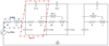 |
Fig. 4 MATLAB model used to extract the voltage time value of each turn. |
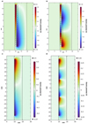 |
Fig. 5 Voltage distribution between turns of a coil. Voltage time rise voltage fixed at 0.5V/ns. Standard coil two rows powered with 1V (a); segmented coil two rows powered with 0.33V (b); standard coil one rows powered with 1V (c); segmented coil one rows powered with 0.33V (d). |
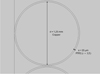 |
Fig. 6 Wire dimensions and materials used in the COMSOL simulation. |
Lumped parameters at 50 MHz. The parameters of the power cable (RC, LC) and the capacitance between the turns (Cij) are considered constant and computed in frequency domain simulations. The other values have been calculated as matrices, with their minimum and maximum values indicated. In the Lij matrix, entries where i = j represent the self-inductances of the turns, while those where i ≠ j correspond to the mutual inductances, labelled as Mi-j in Figure 4.
4 Results
Our assessment procedure applies to two different geometries. In the geometry shown in Figures 5a and 5b, two rows of 27 turns each were placed side by side with the left row in contact with the magnetic core, while in the geometry shown in Figures 5c and 5d, a single row of 54 turns was placed in contact with the magnetic core. These 4 different configurations result in different electric potential maps and threshold values for the elements listed in Table 1.
Considering the coil with a single row of turns, the turns are numbered from top to bottom (turn number 1 is the topmost, while turn number 54 is the bottommost). In contrast, for the coil with two rows of turns, the first turn is the topmost one near the magnetic core, turn 28 is the topmost one farther from the core, and turn 54 is the bottommost one farther from the core. The position of the respective turns is crucial for understanding whether the main breakdown voltage primarily occurs between adjacent turns or between a specific turn and the magnetic core.
In the case of CTAF feeding, the geometry remains the same, but the turns are powered in three separate blocks from top to bottom.
Figure 5 represents the four maps of the electric potential corresponding to the four cited cases (one row with classic feeding [Fig. 5c] and CTAF feeding [Fig. 5d], and two rows with classic feeding [Fig. 5a] and CTAF feeding [Fig. 5b]), where the turns are powered with a step signal going from zero to 1 Volt in 20 nanoseconds for the normal setup, and from zero to 0.33 Volt in 20 nanoseconds for the CTAF setup. From Figure 5, the electric potential at critical points is derivated to obtain the electric field and compare it with the value of 35 kV/cm, which is critical according to Air Paschen's law. The minimum integration distance is chosen at 200 micrometres to simulate discharges with sufficient energy to cause rapid damage to the electrical machine and to ensure the calculation remains on the right-hand side of Paschen's curve. Table 2 provides the found values for the threshold voltage required to obtain an electrical discharge and clearly shows how these values strongly increase by using segmented winding configuration.
In addition, the study reveals that the way the turns are positioned has a significant impact on the breakdown voltage. More specifically, in the case with two rows of turns, the minimum breakdown voltage occurs between two contiguous turns on different rows (especially between number 1 and number 28), and the breakdown voltage between the turns near the core and the core itself is slightly lower but of the same order of magnitude as the turn-to-turn breakdown voltage. In the case with a single row of turns, the minimum breakdown voltage is between the turn and the magnetic core. The latter is much higher if compared with the same position in the case with two rows of turns.
Maximum voltage supply (VDC) without breakdown in the various configurations.
5 Conclusions and prospectives
To summarize, this preliminary study, based on a series of simulations, enables to identify trends regarding the comparison between two coil geometries (the first arranged in a single row and the second arranged in two adjacent vertical rows). Additionally, both configurations are powered by two types of power supply, while producing the same electric machine torque. To clarify, this means that powering the CTAF configuration with one-third of VDC results in the same mechanical characteristics (in terms of torque) as a standard machine based on an equivalent geometry powered with VDC and classical voltage power supply (a single inverter).
The trends identified are as follows: the CTAF configuration allows an increase in the machine's operating voltage by a factor of about 3 without the risk of breakdown. Furthermore, it was shown that when the coil turns are arranged in a single row, the main breakdown voltage occurs between the turn and the magnetic core, while when the coil turns are arranged in two rows, the breakdown voltage is lower and occurs between adjacent turns.
The effect of the power cable is not yet assessed in this article. Indeed, the discrepancies between voltage breakdown with and without feed cable had already been considered in a previous paper [14].
Regarding future work, although trends have been identified, the values obtained currently seem to be strongly dependent on the evaluated lumped parameters, which are frequency dependent. This means that if a different voltage signal is used, the computed values may change. Moreover, the results appear to be highly sensitive to the geometry, and currently, in the production of most electric machines, there is no certainty inside the machine about the exact position of a turn relative to the others. For all these reasons, an experimental study is planned to align the simulated results with real-world data.
Funding
This research received no external funding.
Conflicts of interest
The authors have nothing to disclose.
Data availability statement
Data associated with this article cannot be disclosed due to other reason.
Author contribution statement
Conceptualization, O. Bethoux, E. Labouré, G. Krebs and E. Odic; Methodology and Validation, G. Krebs, N. Lanciotti; Software, Formal Analysis, Data Curation, G. Galli, N. Lanciotti; Writing − Original Draft Preparation, G. Galli; Writing − Review & Editing, G. Galli, N. Lanciotti, O. Bethoux, E. Labouré, G. Krebs, E. Odic.
References
- V. Madonna, P. Giangrande, M. Galea, Electrical Power Generation in Aircraft: Review, Challenges, and Opportunities, IEEE Trans. Transp. Electr. 4, 646 (2018) [CrossRef] [Google Scholar]
- L. Tom, M. Khowja, G. Vakil, C. Gerada, Commercial Aircraft Electrification—Current State and Future Scope, Energies 14, 8381 (2021). https://doi.org/10.3390/en14248381 [CrossRef] [Google Scholar]
- A.S. Abdel-Khalik, A. Massoud, S. Ahmed, Standard Three-Phase Stator Frames for Multiphase Machines of Prime-Phase Order: Optimal Selection of Slot/Pole Combination, IEEE Access 7, 78239 (2019) [CrossRef] [Google Scholar]
- H. Hua, H. Chen, W. Hua, Comparative Investigation of Dual Three-Phase Permanent Magnet Synchronous Machines With Different Winding Configurations, IEEE Trans. Ind. Appl. 60, 3120 (2024) [CrossRef] [MathSciNet] [Google Scholar]
- Q. Zhang, H.J. Raherimihaja, G. Xu, X. Zhang, Design and Performance Analysis of Segmented Three-Phase IPMSM for EVs Integrated Battery Charger, IEEE Trans. Ind. Electron. 68, 9114 (2021) [CrossRef] [Google Scholar]
- E. Hoang, E. Laboure, Electric machine supplied at low voltage and associated multicellular power train, U.S. Patent 10985626B2, 20 April 2021 [Google Scholar]
- G. Rohner, J.W. Kolar, D. Bortis, M. Schweizer, Optimal level number and performance evaluation of Si/GaN multi-level flying capacitor inverter for variable speed drive systems, in 2022 25th International Conference on Electrical Machines and Systems (ICEMS) (Chiang Mai, Thailand, 2022), pp. 1–6. https://doi.org/10.1109/ICEMS56177.2022.9982999 [Google Scholar]
- K. Hazim, G. Parent, S. Duchesne, C. Geuzaine, Frequency-dependent behavior of the lumped parameter model of the windings of electrical machines in transient simulations, in 23rd International Conference on the Computation of Electromagnetic Fields (COMPUMAG) (Cancun, Mexico, 2022) [Google Scholar]
- L. Benmamas, P. Teste, F. Vangraefschepe, G. Krebs, E. Odic et al., Validation d'un modèle de bobinage par analyse fréquentielle et temporelle, in 2nd Symposium de Génie Électrique (SGE 2016) (Grenoble, France, 2016) [Google Scholar]
- G. Galli, H. Hamrita, C. Jammes, M.J. Kirkpatrick, E. Odic et al., Characterization and Localization of Partial-Discharge-Induced Pulses in Fission Chambers Designed for Sodium-Cooled Fast Reactors, IEEE Trans. Nucl. Sci. 65, 2412 (2018) [CrossRef] [Google Scholar]
- J.M. Meek, J.D. Craggs, Electrical Breakdown of Gases (Wiley, 1978) [Google Scholar]
- L. Benmamas, Méthodes d'évaluation du risque de décharges partielles dans le bobinage de machines électriques destinées à la traction automobile, Ph.D. dissertation in electrical engineer, Université Paris Saclay (COmUE), 2017 [Google Scholar]
- H. Ben Ahmed et al., Electric traction chain with segmented power supply, in 23rd European Conference on Power Electronics and Applications (EPE'21 ECCE Europe) (Ghent, Belgium, 2021) [Google Scholar]
- N. Lanciotti et al., Numerical investigation of partial electrical discharge occurrence in electric power system with segmented power supply, in 10ème Conférence Européenne sur les Méthodes Numériques en Electromagnétisme (NUMELEC 2024) (Toulouse, France, 2024) [Google Scholar]
Cite this article as: Noemi Lanciotti, Giacomo Galli, Guillaume Krebs, Olivier Bethoux, Eric Labouré, Emmanuel Odic, Computational study of partial discharge events in electric drives with segmented power supply, Eur. Phys. J. Appl. Phys. 100, 4 (2025), https://doi.org/10.1051/epjap/2025001
All Tables
Lumped parameters at 50 MHz. The parameters of the power cable (RC, LC) and the capacitance between the turns (Cij) are considered constant and computed in frequency domain simulations. The other values have been calculated as matrices, with their minimum and maximum values indicated. In the Lij matrix, entries where i = j represent the self-inductances of the turns, while those where i ≠ j correspond to the mutual inductances, labelled as Mi-j in Figure 4.
All Figures
|
Fig. 1 Theoretical Paschen's curve in air. |
| In the text | |
 |
Fig. 2 Example of standard electric drive (left) and highly modular electric drive (right) [6]. |
| In the text | |
|
Fig. 3 Protocol of simulation study (The black blocks represent the software used while the white blocks describe the computed output values). |
| In the text | |
|
Fig. 4 MATLAB model used to extract the voltage time value of each turn. |
| In the text | |
|
Fig. 5 Voltage distribution between turns of a coil. Voltage time rise voltage fixed at 0.5V/ns. Standard coil two rows powered with 1V (a); segmented coil two rows powered with 0.33V (b); standard coil one rows powered with 1V (c); segmented coil one rows powered with 0.33V (d). |
| In the text | |
|
Fig. 6 Wire dimensions and materials used in the COMSOL simulation. |
| In the text | |
Current usage metrics show cumulative count of Article Views (full-text article views including HTML views, PDF and ePub downloads, according to the available data) and Abstracts Views on Vision4Press platform.
Data correspond to usage on the plateform after 2015. The current usage metrics is available 48-96 hours after online publication and is updated daily on week days.
Initial download of the metrics may take a while.