| Issue |
Eur. Phys. J. Appl. Phys.
Volume 99, 2024
|
|
|---|---|---|
| Article Number | 21 | |
| Number of page(s) | 4 | |
| DOI | https://doi.org/10.1051/epjap/2024240087 | |
| Published online | 09 September 2024 | |
https://doi.org/10.1051/epjap/2024240087
Original Article
Characterisation of barium hexaferrite thin films in microwave frequency band
Hubert Curien Laboratory, Université Jean Monnet de Saint-Etienne, 25 rue Annino, Saint-Etienne 42000, France
* e-mail: This email address is being protected from spambots. You need JavaScript enabled to view it.
Received:
7
May
2024
Accepted:
24
July
2024
Published online: 9 September 2024
Abstract
The characterization of barium hexaferrite thin-films at microwave frequencies is important for determining their electromagnetic properties by measuring the elements of the permeability tensor. Layers of 15 µm were deposited by RF sputtering on a coplanar line. As a result of this deposition and annealing technique, the magnetic moments are mainly oriented in the plane of the layer. By measuring the S parameters under magnetic field conditions, the µ and κ elements of the permeability tensor were extracted and their variations as a function of the applied field were highlighted. Possible applications to absorbent layers are being considered.
Key words: Characterization / microwave / magnetic materials / CPW
© D. Vincent, Published by EDP Sciences, 2024
 This is an Open Access article distributed under the terms of the Creative Commons Attribution License (http://creativecommons.org/licenses/by/4.0) which permits unrestricted use, distribution, and reproduction in any medium, provided the original work is properly cited.
1 Introduction
Knowledge of the electromagnetic properties of ferrites is essential for modeling and designing components and deriving their performance. Numerous studies have been carried out on barium hexaferrite, a hard material that can be used to design self-biased non-reciprocal components [1–4]. Various characterization methods have been developed to extract the constituent parameters of these materials. For example in [5,6] microwave absorption performance of barium hexaferrite multi-nanolayers are characterized. In the same way in [7], the effective permeability of Barium ferrite is obtained by coaxial-line measurement and Nicolson Ross Weir procedure. However, the most of microwave characterization on barium ferrite and substituted barium hexagonal ferrites are made by this method leading to only effective permeability and not to the elements of the permeability tensor [8,9]. Methods for determining elements of the permeability tensor [10–12], and elements of the thin-film tensor [13,14] are fewer in number and more difficult to implement. We will use the latter method, developed in the laboratory, which uses a coplanar line on which a thin layer of barium ferrite has been deposited. It is interesting to note that the magnetic properties of these layers can sometimes be different from those of the bulk material. The study proposed in this article consists of evaluating two elements of the permeability tensor (µ and κ) and studying their variation as a function of a transversely applied field. The study of these parameters is important to design non-reciprocal components when usually the ratio  is an essential parameter.
2 Method
2.1 Measurement cell
The measurement cell shown in Figure 1 consists of a CPW line on which a layer of barium hexaferrite (BaM) has been deposited by RF sputtering. The dimensions of the CPW line cell are slot width W = 40 μm, central line width 72 μm and length arround 16 mm. The biasing magnetic field is applied transversely using an electromagnet.
 |
Fig. 1 Cross section of the measurement cell; s = 72 μm, w = 40 μm and the length 16 mm. |
2.2 Magnetic film parameters
Table 1 shows the characteristics of the layer obtained by RF sputtering. Vibrating-sample magnetometer measurement (VSM) are given in Figure 2.
BaM layer.
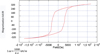 |
Fig. 2 VSM measurement in plane. |
2.3 Permeability measurement
The method is based on a comparison of the properties of a CPW line without a magnetic layer and an identical line with a magnetic layer [13]. From the measurement of the S parameters, the propagation constants (β+ and β– depending on the direction of direct and reverse propagation) are calculated by solving the following equations:
 (1)
(1)
where,

L is the length of the line.
When the layer is non-magnetic or non-magnetized:
 (2)
(2)
The concentration of the electric field in the layer allows a number of approximations to be made, as described in reference [13], and leads to approximate expressions for the elements µ and κ of the effective permeability tensor:

to finally obtain the relations:
 (3)
(3)
with  , ϵrd and ϵrf are the permittivity of the substrate (alumina or non-magnetized ferrite layer) and the permittivity of the ferrite (BaM) respectively.
The ratio  , or “ellipticity” factor, is determined by calculating the fields at the air-magnetic layer interface of the coplanar line and obtained by simulation. To find the permeability tensor of the magnetic layer, it is generally sufficient to multiply the expressions for µ and κ by a factor (filling factor) that depends on the thickness of the layer and the dimensions of the coplanar line used as a test cell [13]. In this article, only the actual constitutive parameters or effective parameters of the loaded line will be considered. These make it possible to determine the gyromagnetic resonance frequency and to envisage the use of the material as a constituent element of non-reciprocal passive components or as an absorber.
3 Experimental results
3.1 Results without applied bias-field
The first results without applied bias-field are given in Figures 3 and 4.
In this configuration the gyromagnetic resonance can be calculated by the relation (Kittel formula [15]):
 (4)
(4)
where Hk is the anisotropy field, Happl the applied bias-field and M the magnetization. In these first measurements, the magnetic layer is demagnetized (M ≈ 0) with no external applied field (Happl = 0) and, in fact, the value of the extra-diagonal component κ is zero for this state of magnetization. The natural resonance frequency is around 46.53 GHz, as function of the anisotropy field, which can be evaluated at 1.64 Tesla or 1.305 × 10³ kA/m, close to the value for bulk material. This confirms that the magnetic moments in domains are rather oriented in the plane with low demagnetizing factors.
It should be noted, however, that the relationship (4) is not applicable to an unsaturated material, as it is difficult to assess the influence of the applied field and the magnetization.
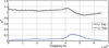 |
Fig. 3 Experimental results without bias-field : |


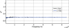 |
Fig. 4 Experimental results: |


3.2 Results with applied bias-field
The applied field is estimated at 160 kA/m between the two poles of an electromagnet. It was applied successively in both directions along the Oy axis (see Fig. 1). Figures 5 and 6 show the curves of µeff and κeff respectively for these two polarization states.
A variation in the resonance frequency is observed due to the increase or decrease of the internal field. The extra-diagonal term κ is no longer zero. The ferrite is in a state of partial magnetization. These experimental results can be compared with models of permeability tensors to assess their validity for this type of material in this frequency band. This comparison is planned with one of the most successful models given as a reference [16]. Once the ferrite has been magnetized, the magnetization will remain remanent. This will be on the main hysteresis cycle or on a possible secondary cycle. We can try to take advantage of non-reciprocal propagation to design a millimeter-band isolator, but it seems difficult to reduce losses in the forward direction. The most promising application seems to be that of an absorber cell or filter. The material can also be used as an absorbent material for electromagnetic shielding.
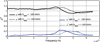 |
Fig. 5 Experimental results: |


 |
Fig. 6 Experimental results: |


4 Application of the material as an absorbent layer
In addition to being used the S-parameters to solve the inverse problem, the S-parameters measurements show the use of this material as a broadband absorber. Figure 7 shows the reflection parameters (S11 and S22), which do not significantly change with the bias-field. The reflection parameters show multiple resonances which are in fact line-length resonances when the half-wavelength of the guided wave corresponds to the length of the line. The reflection parameters remain below −10 dB, which may be sufficient for the intended application, but can be reduced by modifying the line impedance.
Figure 8 shows the transmission parameters (S21 and S12) measured with the magnetic field applied in the plane of the layer and successively in both directions.
The transmission parameters show very high attenuation in both directions of propagation (below −20 dB) over a wide frequency band. This attenuated band is evaluated at over 14 GHz (at −20 dB) and can be adjusted with bias-field. However, it is much more convenient not to use an applied field for this type of application, and the Figure 9 shows the results obtained in this magnetic state. The BAM layer is demagnetized, and the attenuated band is around 15 GHz. The transmission is then reciprocal. These results are obtained for a coplanar line of 16 mm long. Hence, the maximum attenuation can be evaluated as 2.5 dB/mm at 46 GHz.
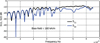 |
Fig. 7 Module in dB of reflection parameters S11 and S22. |
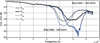 |
Fig. 8 Module in dB of transmission parameters S21 and S12. |
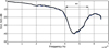 |
Fig. 9 Module in dB of transmission parameters S21 and S12 (demagnetized barium ferrite). |
5 Conclusion
The properties of magnetic layers of barium ferrite show the possible applications of this material as an absorber and its use in a millimetre-band attenuator. Losses are created by the phenomenon of gyromagnetic resonance. This material is not textured and does not have a sufficient Mr/Ms ratio for use in non-reciprocal passive components. Studies have shown that it is difficult to orientate this material deposited in a thin layer, and annealing at high field strength and high temperature remains difficult to implement.
It seems more interesting not to apply a field that requires the use of bulky permanent magnets for the miniaturization of these devices. This line with a layer of barium ferrite can be used as a very wide band filter or as an attenuator for millimeter bands. It is also possible to use such absorbing layers deposited on a metal surface to provide effective shielding. To go further and create millimeter absorbers, it would be interesting to include nano-particles of this type of material in high concentration in polymers to create an absorbent coating in this frequency band.
Funding
This research received no external funding.
Conflicts of interest
The authors have nothing to disclose.
Data availability statement
This article has no associated data generated or analyzed.
Author contribution statement
I am the only author and I have performed these measurements.
References
- W. D'Orazio, K. Wu, IEEE Trans. Microwave Theory Tech. 54, 3675 (2006) [CrossRef] [Google Scholar]
- A. Guennou, P. Quéffélec, P. Gelin, J.L. Mattei, J. Appl. Phys. 99, 505 (2006) [CrossRef] [Google Scholar]
- J. Wang, A. Geiler, P. Mistry, D.R. Kaeli, V.G. Harris, C. Vittoria, J. Magn. Magn. Mater. 324, 991 (2012) [NASA ADS] [CrossRef] [Google Scholar]
- V. Laur, G. Vérissimo, P. Quéffélec, L.A. Farhat, H. Alaaeddine, E. Laroche, G. Martin, R. Lebourgeois, J.P. Ganne, IEEE Trans. Microwave Theory Tech. 63, 4376 (2015) [CrossRef] [Google Scholar]
- E. Handoko, A.B. Susila, I. Sugihartono, M.A. Marpaung, Z. Jalil, M. Alaydrus, J. Phys.: Conf. Ser. 1402, 044068 (2019) [CrossRef] [Google Scholar]
- E. Handoko, S. Budi, I. Sugihartono, M.A. Marpaung, Z. Jalil, A. Taufiq, M. Alaydrus, Mater. Express 10, 1328 (2020) [CrossRef] [Google Scholar]
- D.S. Klygach et al., J. Magn. Magn. Mater. 465, 290 (2018) [CrossRef] [Google Scholar]
- Y. Ding, T.J. Klemmer, T.M. Crawford, J. Appl. Phys. 96, (2004) [Google Scholar]
- S.B. Narang, P. Kaur, S. Bahel, C. Singh, J. Magn. Magn. Mater. 405, 17 (2016) [CrossRef] [Google Scholar]
- A. Chevalier, J. Cortes, J. Lezaca, P. Quéffélec, J. Appl. Phys. 114, 174904 (2013) [CrossRef] [Google Scholar]
- J. Krupka, Meas. Sci. Technol. 29, 092001 (2018) [CrossRef] [Google Scholar]
- J.H. Rowen, W. von Aulock, Phys. Rev. 96, 1151 (1954) [CrossRef] [Google Scholar]
- D. Vincent, T. Rouiller, C. Simovsky, B. Bayard, G. Noyel, IEEE Trans. Microwave Theory Tech. 53, 1174 (2005) [CrossRef] [Google Scholar]
- J. Krupka, Meas. Sci. Technol. 29, 092001 (2018) [CrossRef] [Google Scholar]
- C. Kittel, J. Phys. Radium 12, 291 (1951) [CrossRef] [EDP Sciences] [Google Scholar]
- P. Gelin, P. Quéffélec, IEEE Trans. Magn. 44, 24 (2008) [CrossRef] [Google Scholar]
Cite this article as: Didier Vincent, Characterisation of barium hexaferrite thin films in microwave frequency band, Eur. Phys. J. Appl. Phys. 99, 21 (2024)
All Tables
All Figures
|
Fig. 1 Cross section of the measurement cell; s = 72 μm, w = 40 μm and the length 16 mm. |
| In the text | |
|
Fig. 2 VSM measurement in plane. |
| In the text | |
|
Fig. 3 Experimental results without bias-field : |
| In the text | |
|
Fig. 4 Experimental results: |
| In the text | |
|
Fig. 5 Experimental results: |
| In the text | |
|
Fig. 6 Experimental results: |
| In the text | |
|
Fig. 7 Module in dB of reflection parameters S11 and S22. |
| In the text | |
|
Fig. 8 Module in dB of transmission parameters S21 and S12. |
| In the text | |
|
Fig. 9 Module in dB of transmission parameters S21 and S12 (demagnetized barium ferrite). |
| In the text | |
Current usage metrics show cumulative count of Article Views (full-text article views including HTML views, PDF and ePub downloads, according to the available data) and Abstracts Views on Vision4Press platform.
Data correspond to usage on the plateform after 2015. The current usage metrics is available 48-96 hours after online publication and is updated daily on week days.
Initial download of the metrics may take a while.