| Issue |
Eur. Phys. J. Appl. Phys.
Volume 84, Number 1, October 2018
|
|
|---|---|---|
| Article Number | 10601 | |
| Number of page(s) | 4 | |
| Section | Spintronics, Magnetism, Superconductivity | |
| DOI | https://doi.org/10.1051/epjap/2018180226 | |
| Published online | 21 December 2018 | |
https://doi.org/10.1051/epjap/2018180226
Regular Article
Electromagnetic properties of LTCC-ferrite in the microwave range
1
Université de Lyon, UJM-Saint-Etienne, CNRS, LaHC UMR 5516,
18 rue Benoit Lauras,
42023
Saint-Étienne, France
2
University of Ontario Institute of Technology, Faculty of Engineering and Applied Science,
2000 Simcoe St. N.,
Oshawa,
ON
L1G 0C5, Canada
3
Department of Electrical and Computer Engineering, Royal Military College of Canada,
Kingston,
ON
K7K 7B4, Canada
a e-mail: This email address is being protected from spambots. You need JavaScript enabled to view it.
Received:
24
July
2018
Received in final form:
1
August
2018
Accepted:
26
September
2018
Published online: 21 December 2018
Abstract
The electromagnetic properties of a low temperature co-fired ceramic (LTCC) ferrite in the microwave range have been determined by performing S-parameter measurements of a coplanar waveguide (CPW) cell. An optimization procedure is used to minimize an error function that compares the measured S-parameters to those obtained from electromagnetic simulations based on the spectral domain approach (SDA) method in the saturated state. Using this method, the μ and κ parameters of the permeability tensor are extracted. Other results in the demagnetized and partially magnetized states show a special LTCC-ferrite behavior.
© EDP Sciences, 2018
 This is an Open Access article distributed under the terms of the Creative Commons Attribution License (http://creativecommons.org/licenses/by/4.0), which permits unrestricted use, distribution, and reproduction in any medium, provided the original work is properly cited.
1 Introduction
The electromagnetic properties of magnetic materials are essential for microwave passive component design. Nonreciprocal passive components, such as isolator or circulators, contain a ferrite core. The ferrite material can be completely or partially magnetized by applying a d.c. magnetic field. The permeability is an antisymmetric tensor with components that depend on the physical properties of the medium, and that vary relative to the frequency and the d.c. applied field. Various models may be used to describe the material's electromagnetic behavior. The simplest analytic expressions of the tensor components were derived by Polder [1] for saturated ferrites. Other, more complicated models exist for partially magnetized states [2–6], but their implementation in a broadband frequency range is not convenient, except for the last model which can be considered as the “general permeability tensor”. The integration of microwave passive components is an important issue for the microwave electronic industry. However, classical ferrite substrates do not provide an attractive solution for such a system integration. The main disadvantage of classical ferrite substrates is the use of external magnets as the source for d.c. magnetic fields. This makes the design bulky and difficult to integrate. On the other hand, the production of passive components using ferrite material has interesting prospects when using low temperature co-fired ceramic (LTCC) technology. Several studies have been carried out on a LTCC-ferrite for radio-frequency and microwave applications [7–9]. These designs show promising results for tunable and reconfigurable applications but they rely on theoretical models for the magnetostatic properties of the ferrite substrates. Thus, it is essential that the magnetostatic properties of the ferrite LTCC materials be measured to verify the theoretical models being used. Different methods have also been developed to obtain the dielectric permittivity and magnetic permeability of ferrite materials. Some of them only allow the measurement of the effective permeability and not the tensor components [10], while other methods can give the permittivity and components of the permeability tensor [11,12]. It is worth mentioning here that none of these papers discuss multilayer ferrite LTCC substrates. In reference [13], a nonreciprocal stripline is used to deduce the two main tensor components (μ and κ) in a wide frequency range. There is no simple analytical relation between S-parameters and constitutive parameters (μ, κ and ϵ), thus a numerical optimization procedure is used to match theoretical S-parameters to the measured ones.
In the present work, the same concept is performed on a coplanar waveguide (CPW) cell [14]. The implementation is simpler and the S-parameter measurements can be extended up to higher frequency bands. The proposed CPW broadband method leads to the measurement of two permeability tensor components of the LTCC-ferrite substrate. In this paper, when the LTCC is saturated, only the Polder model is implemented as a first approach. Other permeability models could be easily implemented in future work, if necessary. Incidentally, the CPW structure used for the ferrite material characterization could double as a tunable microwave attenuator.
2 Experiment
2.1 Measurement cell
The dimensions of the CPW (W = 72 μm, S = 40 μm) are well suited to work in the operating frequency band of 1 – 20 GHz (see Fig. 1). The LTCC-ferrite thickness is 1 mm. The S-parameters are measured by a vector network analyzer (VNA) using CPW probes with a classical OSTL calibration procedure. The LTCC-ferrite used in this work is ESL 40012 [14]. The magnetostatic and microwave properties of this substrate were previously reported in the demagnetized state only [7], using multilayer solenoidal and toroidal multilayer transformers. The paper reports saturation magnetization, coercive field and dielectric constant values of 310 kA/m, 10 A/m and 14 (at 9.86 and 27.2 GHz), respectively. The characterization work was carried out at room temperature.
In addition, hysteresis curves at 20 and 100 ∘C, measured using the VSM technique, are shown in Figure 2 and display a soft ferrite behavior. The curves indicate that this material is quite sensitive to temperature and that the magnetization significantly decreases at high temperatures.
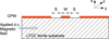 |
Fig. 1 CPW measurement cell. |
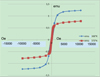 |
Fig. 2 Magnetization curves at 20 and 100 ∘C. |
2.2 Direct and inverse problems
Solving the direct problem consists of finding the S-parameters from the cell dimensions and constitutive parameters.
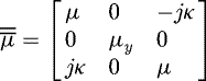
When the ferrite is saturated by a magnetic bias along the y-axis, the Polder model yields the following permeability tensor:
 (1)
with
(1)
with
 and ωm = γμ0Ms, ω0 = γμ0Hi, where Hi is the internal biasing field, Ms is the saturation magnetization and α is the damping factor.
Three permeability parameters, namely, μ, κ and μy, which depend on Ms, Hi α and the relative permittivity ϵr of the LTCC-ferrite, must be found by an optimization technique. A wideband optimization procedure is used to find the frequency spectra of μ and κ by solving the inverse problem over the entire frequency band by matching the S-parameter magnitudes [12].
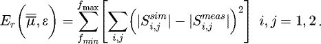
The Levenberg–Marquardt–More algorithm [15] is used because it avoids stopping on local minima when the initial parameters are well chosen. The error function, obtained by comparing the measured S-parameters to the simulated S-parameters (the latter obtained using the SDA method, which is a method of moments in the spectral domain), must be minimized by the optimization procedure.
 (2)
(2)
3 Results
3.1 LTCC-ferrite in the saturated state
The CPW feed line's S-parameters, measured at two different bias field strengths, 115 and 178 kA/m, are shown in Figures 3 and 4, respectively. The d.c. magnetic field is applied using an electromagnet. The close agreement that is observed between the numerical and measured results serves to validate the use of the Polder model.
The tensor permeability components μ and κ are shown in Figure 5.
The material parameters that were extracted from the optimization process are given in Table 1. The material is confirmed to be in the saturated state despite its special composition for compatibility with the co-fired ceramic process. The results indicate that this LTCC-ferrite has properties that are similar to other, saturated bulk ferrite materials. The saturation magnetization (approximately 305 kA/m) is found to be in very good agreement with the one obtained in reference [7] (310 kA/m). The internal magnetic field is given by
 (3)
(3)
The external applied d.c. magnetic field H0 is created by an electromagnet with special poles to transversely apply the magnetic field on the cell. Two applied field values of 115 and 178 kA/m were measured using a magnetometer. Using equation (3), the demagnetizing factor Ny is estimated to be 0.0293 and 0.0424, respectively. According to the sample dimensions (15 mm ×7 mm × 1 mm) and the work in reference [16], these values seem to be correct, but more accurate results can be obtained by using a magnetostatic solver. Another source of error is the magnetometer that is used for the external magnetic bias field measurement, which has an accuracy of ±1 mT or ±0.8 kA/m. In addition, the dimensions of the electromagnet poles can also distort the (assumed) magnetic field uniformity inside the LTCC-ferrite sample. The complete magnetic field biasing system should be studied using a magnetostatic solver.
Despite these issues, these preliminary results provide important information. Table 1 indicates that the ferrite-LTCC damping factor, although higher than that of garnet ferrite, is still sufficiently low to permit the use of this material in the microwave range, above the gyromagnetic frequency band. An example of such an application is the 14.5 GHz microwave circulator with integrated coils [17].
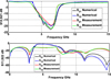 |
Fig. 3 S-parameters: comparison of the measured S-parameters with the S-parameters calculated using the optimization process (transmission parameters and refection parameters) with an applied magnetic field of H0 = 115 kA/m. |
 |
Fig. 4 S-parameters: comparison of the measured S-parameters and the S-parameters calculated using the optimization process (transmission parameters and refection parameters) with an applied magnetic field of H0 = 178 kA/m. |
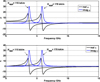 |
Fig. 5 Components μ and κ of the permeability tensor with two applied fields 115 and 178 kA/m, respectively. |
Material constitutive parameters obtained from optimization.
3.2 LTCC-ferrite in nonsaturated state
In contrast, when the material is not in the saturated state, other models must be used, as mentioned in references [8,9]. Figure 6 shows the measured transmission S-parameters of the CPW cell when the material is in the demagnetized state. As expected, high losses are observed up to 10 GHz, probably due a wide band gyromagnetic resonance phenomenon. Although the domain-wall relaxation phenomenon could also be present, it usually appears at lower frequencies for ordinary polycrystalline ferrites such YIG and spinel.
Accordingly, this demagnetized LTCC-ferrite could be used as a wideband absorber up to 10 GHz. The lower loss region above this frequency can be used to design other practical microwave devices, as reported previously [8,9].
The transmission S-parameters of the CPW cell in the partially saturated state are shown in Figure 7 with a low applied field value of 19 kA/m. Losses generally decrease at low frequencies when the bias field is applied, but two loss peaks appear at 1.3 and 5 GHz in the transmission parameter curves. The insertion loss between approximately 6and 7 GHz is substantially reduced under partial and complete saturation, making this CPW structure a tunable attenuator. Although wideband gyromagnetic resonance phenomena appear to be present, no existing magnetic material model can predict this electromagnetic behavior. The available information given in reference [14] indicates that this ferrite-LTCC is composed of a flexible cast film of magnetic powder dispersed in an organic matrix, designed to be fired at 885 ∘C to give a dense body. However, more specific information regarding this particular LTCC-ferrite material is required (composition of the magnetic particles, size distribution etc.) to better understand its unique frequency response as a function of the bias.
 |
Fig. 6 Transmission S-parameters in the demagnetized state. |
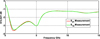 |
Fig. 7 Transmission S-parameters in the partially saturated state (applied field: 19 kA/m). |
4 Conclusion
S-parameter measurements have been performed on a CPW cell to characterize the material parameters of an LTCC-ferrite sample. When saturated, the electromagnetic behavior of the LTCC-ferrite can be predicted using the Polder model, and its electromagnetic performance is found to be similar to that of conventional ferrite materials. When the LTCC-ferrite is demagnetized or partially saturated, its behavior is unique compared to other ferrite materials, with high losses appearing in the low-frequency region that could be due to a wideband magnetic resonance and perhaps a domain-wall relaxation phenomenon. Therefore, LTCC-ferrite materials must be used in the saturated state for the design of nonreciprocal components such as circulators and isolators. This material is useful for high-frequency applications that require high permeability and can be used in the low-loss region for antenna applications or inductance designs. In conclusion, the LTCC process applied to ferrite materials is an important development that allows new integrated microwave magnetic components to be designed. Although dielectric LTCC layers have been widely used to design complex compact microwave devices, this technology now also offers high-performance LTCC-ferrite material as well.
Author contribution statement
Langis ROY, Farhan GHAFFAR of University of Ontario Institute of Technology and Joey Bray of Royal Military College of Canada, Kingston, worked to supervise a Ph.D. student, in with collaboration between France and Canada. This work was aiming to perform a LTCC circulator. They participate to the characterization and to the study of this material. Samples have been fabricated in Canada, and both measured in France and in Canada by vector network analyzer in microwave range.
References
- D. Polder, Philos. Mag. 40, 99 (1949) [Google Scholar]
- G.T. Rado, Phys. Rev. 89, 529 (1953) [Google Scholar]
- E. Schloemann, Appl. Phys. 41, 204 (1970) [CrossRef] [Google Scholar]
- J.J. Green, F. Sandy, IEEE Trans. Microw. Theory Tech. MTT-22, 641 (1974) [Google Scholar]
- M. Igarashi, Y. Naïto, IEEE Trans. Microw. Theory Tech. MTT-29, 568 (1981) [Google Scholar]
- Ph. Gelin, P. Quéffélec, IEEE Trans. Magn. 44, 24 (2008) [Google Scholar]
- A. Shamim, J.R. Bray, N. Hojjat, L. Roy, IEEE Trans. Compon Packaging Manuf. Technol. 1, 999 (2011) [Google Scholar]
- F.A. Ghaffar, J.R. Bray, A. Shamim, IEEE Trans. Antennas Propag. 62, 1238 (2014) [Google Scholar]
- A. Nafe, A. Shamim, IEEE Trans. Microw. Theory Tech. 11, 1238 (2014) [Google Scholar]
- O. Luukkonen, S.I. Maslovski, S.A. Tretyakov, IEEE Antennas Wirel. Propag. Lett. 10, 1295 (2011) [Google Scholar]
- P. Queffélec, M. Le Floc'h, Ph. Gelin, IEEE Trans. Microw. Theory Tech. 48, 1344 (2000) [Google Scholar]
- A. Chevalier, J. Cortes, J. Lezaca, P. Queffélec, J. Appl. Phys. 114, 174904 (2013) [Google Scholar]
- D. Vincent, T. Rouiller, C. Simovsky, B. Bayard, G. Noyel, IEEE Trans. Microw. Theory Tech. 53, 1174 (2005) [Google Scholar]
- ESL Electro-Science Specification Data Sheet: Magnetic Tape 40012. Available at http://www.electroscience.com/pdf/40012.pdf [Google Scholar]
- J.J. More, The Levenberg-Marquardt Algorithm: Implementation and Theory (Springer, Berlin, 1978) [Google Scholar]
- A. Aharoni, J. Appl. Phys. 83, 3432 (1998) [Google Scholar]
- S. Yang, D. Vincent, J.R. Bray, L. Roy, IEEE Trans. Compon. Packaging Manuf. Technol. 5, 879 (2015) [Google Scholar]
Cite this article as: Didier Vincent, Langis Roy, Farhan Ghaffar, Joey R. Bray, Electromagnetic properties of LTCC-ferrite in the microwave range, Eur. Phys. J. Appl. Phys. 84, 10601 (2018)
All Tables
All Figures
|
Fig. 1 CPW measurement cell. |
| In the text | |
|
Fig. 2 Magnetization curves at 20 and 100 ∘C. |
| In the text | |
|
Fig. 3 S-parameters: comparison of the measured S-parameters with the S-parameters calculated using the optimization process (transmission parameters and refection parameters) with an applied magnetic field of H0 = 115 kA/m. |
| In the text | |
|
Fig. 4 S-parameters: comparison of the measured S-parameters and the S-parameters calculated using the optimization process (transmission parameters and refection parameters) with an applied magnetic field of H0 = 178 kA/m. |
| In the text | |
|
Fig. 5 Components μ and κ of the permeability tensor with two applied fields 115 and 178 kA/m, respectively. |
| In the text | |
|
Fig. 6 Transmission S-parameters in the demagnetized state. |
| In the text | |
|
Fig. 7 Transmission S-parameters in the partially saturated state (applied field: 19 kA/m). |
| In the text | |
Current usage metrics show cumulative count of Article Views (full-text article views including HTML views, PDF and ePub downloads, according to the available data) and Abstracts Views on Vision4Press platform.
Data correspond to usage on the plateform after 2015. The current usage metrics is available 48-96 hours after online publication and is updated daily on week days.
Initial download of the metrics may take a while.