| Issue |
Eur. Phys. J. Appl. Phys.
Volume 85, Number 2, February2019
|
|
|---|---|---|
| Article Number | 21301 | |
| Number of page(s) | 6 | |
| Section | Surfaces and Interfaces | |
| DOI | https://doi.org/10.1051/epjap/2019180149 | |
| Published online | 28 February 2019 | |
https://doi.org/10.1051/epjap/2019180149
Regular Article
Comparative study of nitrogen implantation effect on mechanical and tribological properties of Ti-6Al-4V and Ti-10Zr-10Nb-5Ta alloys
1
Institut FEMTO-ST (CNRS, UFC, UBFC, ENSMM, UTBM) ENSMM, 26 rue de l’Epitaphe, 25030 Besançon, France
2
R&D Consulting & Services, Calea Rahovei str. no. 266-268, Sector 5, Bucharest, Romania
* e-mail: This email address is being protected from spambots. You need JavaScript enabled to view it.
Received:
15
May
2018
Received in final form:
6
December
2018
Accepted:
28
January
2019
Published online: 28 February 2019
Abstract
The effect of nitrogen implantation on mechanical and tribological properties of Ti-6Al-4V and Ti-10Zr-10Nb-5Ta alloys was studied. Increasing implantation dose from 1 × 10¹⁶ N+/cm2 to 2 × 10¹⁷ N+/cm2 leads to increase gradually both hardness and Young's modulus. The results show that implantation of 2 × 10¹⁷ N+/cm2 allowed to double the value of Young's modulus and to triple the value of hardness. Friction tests that have been conducted against 100Cr6 steel and alumina balls showed that tribological behavior of the two alloys depend on the nature of the counterpart material and is strongly affected by the implanted dose of nitrogen.
© EDP Sciences, 2019
 This is an Open Access article distributed under the terms of the Creative Commons Attribution License (http://creativecommons.org/licenses/by/4.0), which permits unrestricted use, distribution, and reproduction in any medium, provided the original work is properly cited.
1 Introduction
Due to the formation of very stable, continuous, highly adherent and protective oxide on their surface [1,2], titanium alloys show an excellent resistance to corrosion. In addition, since they are biocompatible and have low density and high specific strength, they are being increasingly used for medical implants.
Ti-6Al-4V is the most popular alloy that is used in numerous industrial and medical applications. Nevertheless, since the toxicity of aluminum and vanadium has been reported by several studies [3,4], new Al and V free beta-type titanium based alloys have been developed. These new materials contain non-toxic elements such niobium, zirconium and tantalum that allow the formation of chemically stable passivating film. Nb stabilizes TiO2 while Zr and Ta form ZrO2 and Ta2O5 which are known to be very chemically stable and very protective [5,6].
Beta-type titanium based alloys with various compositions have been elaborated and studied by numerous researchers: Ti-29Nb-13Ta-4Zr [7], Ti-10Zr-10Nb-5Ta [8], Ti-Nb [9,10], Ti-15Mo-3Nb-3Al [11], Ti6-Al7-Nb [12], Ti-6Al-4V-1Zr [13]. In all these studies, the authors reported the high potential of these materials to be used for medical implants.
Generally titanium based alloys are used after a specific coating treatment to enhance their ability to form chemical strong bonds with living bone [13–16]. Among all the techniques of surface treatment, ion implantation offers the advantages to modify both mechanical and chemical properties of the treated materials without affecting the surface finish. Several studies have focused on the modifications induced by nitrogen implantation in titanium and titanium alloys and all of them reported an improvement of mechanical properties [17–19]. In the case of Ti-6Al-4V, the improvement of mechanical properties after nitrogen implantation was correlated with the precipitation of hard δ-TiN layer and the apparition of compressive elastic stress in the residual α-Ti1− x N x matrix [20]. In [21], the authors reported that nitrogen implantation into Ti-6Al-4V enhanced its corrosion resistance in 0.6 M NaCl solution. However, nitrogen ion implantation at high doses may be detrimental with regards to corrosion [22] and the best corrosion resistance has been achieved for an optimum dose of 1 × 10¹⁷ N+/cm2 [23].
In another study [24], ZrNbTaTiW films, prepared by magnetron sputtering deposition, were implanted with increasing doses of nitrogen ranging from 1 × 10¹⁷ ions/cm2 to 4 × 10¹⁷ ions/cm2 and characterized by nanoindentation tests. It has been found that hardness and Young's modulus increase gradually with increasing implantation dose and reach maximum values of 13.5 GPa (hardness) and 178.9 GPa (Young's modulus) after an implantation dose of 2 × 10¹⁷ ions/cm2. This increase of mechanical properties was attributed to the formation of a mixed layer of oxides and nitrides: TaN, TiN, NbN, ZrO2. The authors showed also that with further increasing of implantation doses, the hardness and Young's modulus slightly decrease due to over-stoichiometric nitrogen ions or re-sputtering effect.
In a previous paper [8], we have conducted a comparative study of corrosion and tribocorrosion between Ti-6l-4V and Ti-10Zr-10Nb-5Ta alloy and we have shown that the latter has better electrochemical behavior (rate of passivation and resistance to corrosion). In the present study, we report new results concerning the effect of nitrogen implantation on mechanical and tribological properties of these alloys when sliding against 100Cr6 steel or alumina.
2 Materials and methods
Ti-6Al-4V and Ti-10Zr-10Nb-5Ta alloys were respectively obtained from Stainless (France) and R&D Consulting & Services (Bucharest, Romania).
Samples of the two alloys were examined using X-ray microanalysis (EDX) facility. The spectra of the analysis are shown in Figure 1A and B and the chemical compositions deduced from these analyses are as follows: Ti-6Al-4V (Ti: 90.46%, Al:7.56%, V:1.98%), Ti-10Zr-10Nb-5Ta (Ti: 72.2%, Zr: 10.8%, Nb:11.2%, Ta:5.8%).
Metal samples were first grinded with SiC papers down to grad 1000 and then polished with diamond solution down to 1 μm. Ultimately, they were cleaned in an ultrasonic bath and rinsed with ethanol. Ion implantations were conducted at 50 KeV at various doses (1 × 10¹⁶ N+/cm2, 5 × 10¹⁶ N+/cm2 and 2 × 10¹⁷ N+/cm2) using IRMA implanter of the CSNSM (Orsay, France) [25].
Since the nitrogen concentration may be approximated by a Gaussian, the parameters of implantation calculated using the TRIM program [26,27] are given in Table 1.
Hardness and Young's modulus values were obtained using a CSM Instruments Nanoindention Tester. Friction tests have been conducted using an experimental device constituted by a ball-on-disc nano-tribometer that has been presented in previous papers [28,29]. Tests were carried out at ambient air and room temperature under an applied load of 100 mN .The riders were spheres of polycrystalline alumina (hardness: 1650 HV) or 100Cr6 steel (hardness: 720 HV) with a diameter of 1.5 mm. The motion was reciprocating with a frequency of 0.35 Hz. The length of the sliding distance was 1 mm and the test duration was 4.75 minutes corresponding to a total sliding distance of 180 mm and 100 cycles.
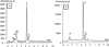 |
Fig. 1 EDX spectrums of Ti-10Zr-10Nb-5Ta (A) and Ti-6Al-4V (B) alloys. |
Implantation parameters. Rp is the mean projected range of ions, ΔRp is the standard deviation of the distribution and C(Rp ) is the maximum of nitrogen concentration at depth Rp .
3 Results and discussion
3.1 Hardness and young's modulus measurements
Figures 2 and 3 show values of hardness and Young modulus of Ti-10Zr-10Nb-5Ta and Ti-6Al-4V alloys before and after implantation of various doses of nitrogen: 1 × 10¹⁶ N+/cm2, 5 × 10¹⁶ N+/cm2 and 2 × 10¹⁷ N+/cm2.
For Ti-10Zr-10Nb-5Ta, implantation of the highest dose allows to (almost) double the value of Young modulus and to triple the value of hardness. These values jump from respectively from 85 GPa and 480 HV for the unimplanted material to 140 GPa and 1350 HV after implantation of 2 × 10¹⁷ N+/cm2. For Ti-6Al-4V, the increase of hardness after ion implantation is comparable to the one observed for Ti-10Zr-10Nb-5Ta whereas Young's modulus increases more slowly.
It appears clearly that mechanical properties of the alloys increase gradually with increasing implantation dose. This result may be explained by the formation of nitrides such as, e.g., TiN, ZrN, TaN, NbN, AlN as has been reported in previous works [5,6,30,31]. Theses phases have been also identified by XPS analysis in the present study. Figure 4 shows N1s region for Ti-10Zr-10Nb-5Ta alloy. The figure shows an important peak that situates around 396 eV. It corrspond to Zr-N and Ti-N bonds whose binding energies are very close each other and situates at 396.7 eV for TiN and 396.5 eV for ZrN. In addition to this first peak, one can see two shoulder peaks that situates at 397 eV and 397.8 eV. They correspond respectively to TaN and NbN.
Figure 5 shows the Al2p spectrum. On can see that Al2p peak corresponding to Al–N bond is splitted into a higher intensity peak corresponding to Al2p3/2 at 73.7 eV binding energy and a lower intensity peak that appears as a shoulder peak corresponding to Al2p1/2 at 74.8 eV binding energy position.
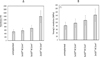 |
Fig. 2 Hardness (A) and Young's modulus (B) of Ti-10Zr-10Nb-5Ta unimplanted and implanted with various doses of nitrogen. |
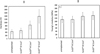 |
Fig. 3 Hardness (A) and Young's modulus (B) of Ti-6Al-4V alloys unimplanted and implanted with various doses of nitrogen. |
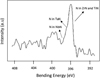 |
Fig. 4 XPS spectra of N1s region for nitrogen implanted Ti-10Zr-10Nb-5Ta alloy. |
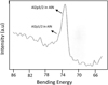 |
Fig. 5 XPS spectra of Al2p3/2 and Al2p1/2 in Al-N bond for nitrogen implanted Ti-6Al-4V. |
3.2 Friction tests
3.2.1 Ti-10Zr-10Nb-5Ta alloy
The variation of friction coefficient during sliding against an alumina ball is shown in Figure 6A. One can see that the evolution of friction coefficient of the unimplanted specimen and the specimen implanted with the lowest dose of nitrogen show important and rapid oscillations indicating seizure and surface wear.
The friction coefficient oscillates rapidly between 0.1 and 0.5 and examination of the wear track reveals material removal (Fig. 6B and C). The specimens implanted with higher doses (5 × 10¹⁶ N+/cm2 and 2 × 10¹⁷ N+/cm2) did not suffer any wear and they show similar value of friction coefficient that is stable during sliding and situates between 0.14 and 0.16 (Fig. 6A).
Additional tests have been performed on the specimens implanted with the highest doses during 150 min instead of 5 min. The evolution of friction coefficient with time is presented in Figure 7. Friction coefficient increases gradually during sliding passing from 0.13 to 0.23. It still shows lower values than those obtained for the unimplanted specimen or the specimen implanted with 1 × 10¹⁶ N+/cm2. In addition, the strong oscillations indicating seizure between the rubbing surfaces does not appear indicating a good resistance to wear. Wear rate has been measured at the end of the tests and the obtained results show that wear is much lower for samples implanted with the highest doses in comparison with the unimplanted specimen or the one implanted with the lowest dose. Indeed, wear rate is of 4 × 10⁻⁷ mm3 N−1 m−1 and 2 × 10⁻⁶ mm3 N−1 m−1 respectively for the specimen implanted with 2 × 10¹⁷ N+/cm2 and 5 × 10¹⁶ N+/cm2 whereas it is in the range of 0.45 × 10⁻⁴ to 1.38 × 10⁻⁴ mm3 N−1 m−1 for the unimplanted specimen and for the one implanted with 1 × 10¹⁶ N+/cm2.
Friction tests conducted against the 100Cr6 steel balls (Fig. 8A) show that ion implantation affects neither friction coefficient nor wear of the sample. Identical friction coefficient value of about 0.12 was obtained for all the specimen tested and no wear has been detected. Material transfer from the steel ball on the implanted titanium alloy sample was observed (Fig. 8B). Indeed X-ray microanalysis spectra shows the presence of iron on the transferred material layer (Fig. 9B). One can also see the presence of a high peak of oxygen indicating that a probable oxidation of iron takes place during friction leading to the formation of iron oxide on the surface of the Ti-10Zr-10Nb-5Ta alloy.
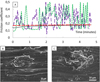 |
Fig. 6 (A) Variation of friction coefficient with time for Ti-10Zr-10Nb-5Ta when sliding against an alumina ball. (B) and (C) show respectively wear debris on the track for the unimplanted specimen and the specimen implanted with the lowest dose. Unimplanted ( |


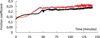 |
Fig. 7 Long duration friction tests conducted on the two higher implanted samples: 5 × 10¹⁶ N+/cm2 ( |


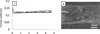 |
Fig. 8 (A) Variation of friction coefficient with time for Ti-10Zr-10Nb-5Ta when sliding against a 100Cr6 steel ball. (B) shows metal transfer from the steel ball on the surface of Ti-10Zr-10Nb-5Ta sample. Unimplanted ( |


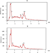 |
Fig. 9 EDX spectrums outside (A) and inside (B) the wear track on Ti-10Zr-10Nb-5Ta after sliding against a steel ball. Material transfer (Fe) from the ball has been detected inside the wear track. |
3.2.2 Ti-6Al-4V alloy
Whatever the specimen tested (implanted or unimplanted), during sliding against 100Cr6 ball, friction coefficient values showed oscillating pattern (stick slip) and varied between 0.05 and 0.35 indicating that seizure occurs at the interface (Fig. 10A). The surface of the material suffers significant wear. It seems that adhesive wear takes place leading to an important material removal (Fig. 10B and C). The wear debris generated during wear may act as abrasive material leading to increase material loss during the wear test.
When sliding against the alumina ball, we obtain identical results as those found in the case of the 100Cr6 steel ball except for the specimen implanted with the highest dose of 2 × 10¹⁷ N+/cm2. For this specimen friction coefficient shows a low value that increases slowly during sliding passing from 0.15 (starting value test) to 0.25 (end of test) (Fig. 11). In addition no wear has been observed on the surface of the material.
Comparison between Ti-6Al-4V and Ti-10Zr-10Nb-5Ta alloys makes it possible to say that Ti-6Al-4V presents the worst tribological behavior when sliding against 100Cr6 steel. This behavior can be explained by tribochemical reactions that takes place between Ti-6Al-4V and counterpart material leading to adhesive wear and high friction coefficient as has been reported in [32]. Identical result has been pointed out in [33] where the authors studied tribological behavior of TiAl intermetallics when sliding against steel or alumina. The presence of aluminium is probably the main cause that leads to the formation of strong jonctions at the interface between the rubbing surfaces and consequently to adhesive wear and high friction coefficient. Indeed, this behavior may be attributed to the high chemical activity of aluminum and to its low melting point that may be reached during friction test [34].
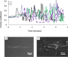 |
Fig. 10 (A) Variation of friction coefficient with time for Ti-6Al-4V when sliding against a 100Cr6 steel ball. (B) Shows the wear track at the end of the tests. (C) Is an enlargement of (B). Identical result was obtained for all the specimens tested (whatever the counterpart surface, alumina or 100Cr6 steel) except the one implanted at the highest dose of 2 × 10¹⁷ N+/cm2 when sliding against an alumina ball. In this case, no wear was detected. |
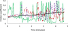 |
Fig. 11 Variation of friction coefficient with time for Ti-6Al-4V when sliding against an alumina ball. Unimplanted ( |


4 Conclusion
Ti-6Al-4V and Ti-10Zr-10Nb-5Ta alloys were implanted with nitrogen at three doses 1 × 10¹⁶ N+/cm2, 5 × 10¹⁶ N+/cm2 and 2 × 10¹⁷ N+/cm2. The effect of ion implantation on mechanical and tribological properties of the materials was studied. The following is a summary of the results obtained:
-
Nitrogen ion implantation leads to increase hardness and Young's modulus for the two materials in quite same way.
-
During friction tests, whatever the counter ball (100Cr6 steel or alumina), unimplanted and low-fluence implanted Ti-6Al-4V alloy (1 × 10¹⁶ N+/cm2 and 5 × 10¹⁶ N+/cm2) show a poor tribological behavior, characterized by an important stick-slip during friction and an important wear by material removal. The specimen implanted at the highest dose of 2 × 10¹⁷ N+/cm2 shows a low and stable friction coefficient and a good resistance to wear when sliding against alumina ball whereas high friction coefficient and wear were obtained when sliding against 100Cr6 steel ball.
-
Implanted and unimplanted Ti-10ZR-10Nb-5Ta alloy present a low friction coefficient when sliding against a steel ball. In contrast when sliding against an alumina ball unimplanted specimen and the specimen implanted at 1 × 10¹⁶ N+/cm2 adhere to alumina leading to a high friction coefficient and an important wear whereas implanted specimens at 5 × 10¹⁶ N+/cm2 and 2 × 10¹⁷ N+/cm2 did not suffer any wear and present low and stable friction coefficient without stick slip.
Acknowledgments
This work was supported by OSEO (project FIMED under contract No A0907009I).
Author contribution statement
S. Ivanescu has elaborated and provided the Ti-10Zr-10Nb-5Ta alloy specimens. S. Carquigny has conducted the tribological tests. J. Takadoum has conducted the surface analysis and wrote the paper.
References
- M.J. Donachie, Titanium: A technical guide (ASM International, 2000) [Google Scholar]
- L.H. Hihara, R.P.I. Adler, R.M. Latanision (editors), Environnemental degradation of advanced and traditional engineering materials (CRC Press, 2014) [Google Scholar]
- S. Sanchez-Iglesias, E. Mendez-Alvarez, J. Iglesias-Gonzalez, A. Munoz-Patino, I. Sanchez-Sollero, J.L. Labandeira-Garcia, R. Soto-Otero, J. Neurochem. 109 , 879 (2009) [CrossRef] [PubMed] [Google Scholar]
- H. Mishibata (editor), Vanadium Biochemical and Molecular Biological Approaches (Springer, 2012) [Google Scholar]
- E. Vasilescu, P. Drob, D. Ionita, S. Ivanescu, C. Vasilescu, Int. J. Environ. Sci. Dev. 1 , 31 (2010) [CrossRef] [Google Scholar]
- N.S. More, N. Diomidis, S.N. Paul, M. Roy, S. Mischler, Mater. Sci. Eng. C 31 , 400 (2011) [CrossRef] [Google Scholar]
- T. Akahori, M. Niinomi, M. Nakai, T. Kasuga, M. Ogawa, Mater. Trans. 49 , 365 (2008) [CrossRef] [Google Scholar]
- J. Takadoum, J. El Mansouri, S. Ivanescu, D. Stanciu, in 2012 MRS Spring Meeting, San Francisco, CA, Materials Research Society mrss12-1464-rr 06–06 [Google Scholar]
- B. Piotrowski, AA. Baptista, E. Patoor, P. Bravetti, A. Eberhardt, P. Laheurte, Mater. Sci. Eng. C 38 , 151 (2014) [CrossRef] [Google Scholar]
- L.M. da Silva, A.P. Rosifini Alves Claro, M.A.R. Buzalaf, C.R. Grandini, Mater. Res. 15 , 355 (2012) [CrossRef] [Google Scholar]
- L. Mohan, C. Anandan, V.K. William Grips, J. Mater. Sci. Mater. Med. 24 , 623 (2013) [CrossRef] [PubMed] [Google Scholar]
- Z. Cai, G. Zhang, Y. Zhu, M. Shen, L. Wang, M. Zhu, Tribol. Int. 59 , 312 (2013) [Google Scholar]
- E. Vasilescu, P. Drob, D. Ionita, S. Ivanescu, C. Vasilescu, Int. J. Environ. Sci. Dev. 1 , 31 (2010) [CrossRef] [Google Scholar]
- K. Neoh, X. Hu, D. Zheng, E. Kang, Biomaterials 33 , 2813 (2012) [CrossRef] [PubMed] [Google Scholar]
- S. Subramaniam, Y. Fang, S. Sivasubramanian, F. Lin, C. Lin, Biomaterials 74 , 99 (2016) [CrossRef] [PubMed] [Google Scholar]
- T.R. Rautray, R. Narayanan, K. Kim, Prog. Mater. Sci. 56 , 1137 (2011) [Google Scholar]
- J.C.M.J. Pivin, F. Pons, J. Takadoum, H.M. Pollock, G. Farges, J. Mater. Sci. 22 , 1087 (1987) [Google Scholar]
- M. Ueda, M.M. Silva, C. Otani, H. Reuther, M. Yatsuzuka, C.M. Lepienski, L.A. Berni, Surf. Coat. Technol. 169–170 , 408 (2003) [Google Scholar]
- D. Krupa, E. Jezierska, J. Baszkiewicz, M. Kamiński, T. Wierzchoń, A. Barcz, Surf. Coat. Technol. 79 , 240 (1996) [Google Scholar]
- R. Hutchings, Mater. Sci. Eng. 69 , 129 (1985) [CrossRef] [Google Scholar]
- G.S. Savonova, M. Ueda, R.M. Oliveira, C. Otania, Surf. Coat. Technol. 206 , 2017 (2011) [Google Scholar]
- R. Asokamani, R. Balu, N. Bhuvaneswaran, U.K. Mudali, in Proceedings of seventh international symposium on electrochemical methods in corrosion research (EMCR), Hungary , 2000, p. 110 [Google Scholar]
- D. Krupa, J. Baszkiewicz, E. Jezierska, J. Mizera, T. Wierzchon, A. Barcz et al., Surf. Coat. Technol. 111 , 86 (1999) [Google Scholar]
- X. Feng, G. Tang, X. Ma, M. Sun, L. Wang, Nucl. Instr. Methods Phys. Res. B 301 , 29 (2013) [CrossRef] [Google Scholar]
- J. Chaumont, F. Lalu, M. Salomé, A.M. Lamoise, H. Bernas, Nucl. Instr. Methods B 9 , 344 (1981) [Google Scholar]
- J.P. Biersack, L.G. Hazgmark, Nucl. Instr. Methods 174 , 257 (1980) [NASA ADS] [CrossRef] [Google Scholar]
- J.P. Biersack, Nucl. Instr. Methods 182–183 , 199 (1981) [CrossRef] [Google Scholar]
- P. Stempfle, J. Takadoum, Tribol. Int. 48 , 35 (2012) [Google Scholar]
- A. Domatti, P. Stempfle, P. Carrière, J. Takadoum, Tribol. Lett. 51 , 207 (2013) [Google Scholar]
- Y. Miyagawa, S. Nakao, K. Baba, R. Hatada, M. Ikeyama, S. Miyagawa, Surf. Coat. Technol. 103–104 , 323 (1998) [Google Scholar]
- S. Drob, V. Cora, P. Drob, E. Vasilescu, D. Gordin, T. Gloriant, J. Miner. Metals Mater. Soc. 67 , 818 (2015) [CrossRef] [Google Scholar]
- J. Qu, P.J. Blau, T.R. Watkins, O.B. Cavin, N.S. Kukarni, Wear 258 , 1348 (2005) [Google Scholar]
- C.X. Li, J. Xia, H. Dong, Wear 261 , 693 (2006) [Google Scholar]
- J. Takadoum, C. Roques-Carmes, Surf. Coat. Technol. 52 , 153 (1992) [Google Scholar]
Cite this article as: Stéphanie Carquigny, Jamal Takadoum, Steliana Ivanescu, Comparative study of nitrogen implantation effect on mechanical and tribological properties of Ti-6Al-4V and Ti-10Zr-10Nb-5Ta alloys, Eur. Phys. J. Appl. Phys. 85, 21301 (2019)
All Tables
Implantation parameters. Rp is the mean projected range of ions, ΔRp is the standard deviation of the distribution and C(Rp ) is the maximum of nitrogen concentration at depth Rp .
All Figures
|
Fig. 1 EDX spectrums of Ti-10Zr-10Nb-5Ta (A) and Ti-6Al-4V (B) alloys. |
| In the text | |
|
Fig. 2 Hardness (A) and Young's modulus (B) of Ti-10Zr-10Nb-5Ta unimplanted and implanted with various doses of nitrogen. |
| In the text | |
|
Fig. 3 Hardness (A) and Young's modulus (B) of Ti-6Al-4V alloys unimplanted and implanted with various doses of nitrogen. |
| In the text | |
|
Fig. 4 XPS spectra of N1s region for nitrogen implanted Ti-10Zr-10Nb-5Ta alloy. |
| In the text | |
|
Fig. 5 XPS spectra of Al2p3/2 and Al2p1/2 in Al-N bond for nitrogen implanted Ti-6Al-4V. |
| In the text | |
|
Fig. 6 (A) Variation of friction coefficient with time for Ti-10Zr-10Nb-5Ta when sliding against an alumina ball. (B) and (C) show respectively wear debris on the track for the unimplanted specimen and the specimen implanted with the lowest dose. Unimplanted ( |
| In the text | |
|
Fig. 7 Long duration friction tests conducted on the two higher implanted samples: 5 × 10¹⁶ N+/cm2 ( |
| In the text | |
|
Fig. 8 (A) Variation of friction coefficient with time for Ti-10Zr-10Nb-5Ta when sliding against a 100Cr6 steel ball. (B) shows metal transfer from the steel ball on the surface of Ti-10Zr-10Nb-5Ta sample. Unimplanted ( |
| In the text | |
|
Fig. 9 EDX spectrums outside (A) and inside (B) the wear track on Ti-10Zr-10Nb-5Ta after sliding against a steel ball. Material transfer (Fe) from the ball has been detected inside the wear track. |
| In the text | |
|
Fig. 10 (A) Variation of friction coefficient with time for Ti-6Al-4V when sliding against a 100Cr6 steel ball. (B) Shows the wear track at the end of the tests. (C) Is an enlargement of (B). Identical result was obtained for all the specimens tested (whatever the counterpart surface, alumina or 100Cr6 steel) except the one implanted at the highest dose of 2 × 10¹⁷ N+/cm2 when sliding against an alumina ball. In this case, no wear was detected. |
| In the text | |
|
Fig. 11 Variation of friction coefficient with time for Ti-6Al-4V when sliding against an alumina ball. Unimplanted ( |
| In the text | |
Current usage metrics show cumulative count of Article Views (full-text article views including HTML views, PDF and ePub downloads, according to the available data) and Abstracts Views on Vision4Press platform.
Data correspond to usage on the plateform after 2015. The current usage metrics is available 48-96 hours after online publication and is updated daily on week days.
Initial download of the metrics may take a while.