| Issue |
Eur. Phys. J. Appl. Phys.
Volume 83, Number 3, September 2018
Materials for Energy harvesting, conversion and storage (Icome 2017)
|
|
|---|---|---|
| Article Number | 30903 | |
| Number of page(s) | 9 | |
| Section | Physics of Energy Transfer, Conversion and Storage | |
| DOI | https://doi.org/10.1051/epjap/2018180160 | |
| Published online | 26 October 2018 | |
https://doi.org/10.1051/epjap/2018180160
Regular Article
Intensification of a flat solar collector efficiency★
1
Département de Physique, Faculté de Sciences, Université de Batna, Algeria
2
Aix-Marseille University, CNRS, IUSTI UMR 7343,
5 rue Enrico Fermi,
13453
Marseille Cedex 13, France
* e-mail: This email address is being protected from spambots. You need JavaScript enabled to view it.
Received:
25
May
2018
Accepted:
19
September
2018
Published online: 26 October 2018
Abstract
An experimental study was carried out to investigate the intensification of the efficiency of a flat solar collector. To achieve this aim, we investigated the effect of the thickness of the air gap between the glazing cover and the plate absorber and the effect of presence of transparent partitions in the air gap. Indeed, when the thickness of the air gap is increased, the natural convection is intensified, which induces high thermal losses on the front part of the collector. The result of this study highlights that thicknesses larger than the reference one, given by the manufacturer, decrease the efficiency, while thicknesses smaller than the reference one increase the efficiency. The presence of transparent partitions in the air gap leads to the weakening of the natural convection and thus to the enhancement of the solar collector efficiency. Two situations were studied. In the first one, only transverse partitions were placed in the air gap; in the second one, longitudinal partitions were added to the transverse ones to form a crossed structure of partitions. The obtained results showed that in both situations the enhancement of the efficiency is significant and that the crossed structure induces the better efficiency.
Contribution to the topical issue “Materials for Energy harvesting, conversion and storage (Icome 2017)”, edited by Jean-Michel Nunzi, Rachid Bennacer, and Mohammed El Ganaoui.
© F.-Z. Ferahta and C. Abid, published by EDP Sciences, 2018
 This is an Open Access article distributed under the terms of the Creative Commons Attribution License (http://creativecommons.org/licenses/by/4.0), which permits unrestricted use, distribution, and reproduction in any medium, provided the original work is properly cited.
1 Introduction
Applications of solar energy systems for various domains, such the production of hot water, need efficient solar collectors [1–3]. High efficiency can be achieved when thermal losses are reduced. The heat losses are mainly due to the radiative and convective exchanges between the glazing cover and the environment. The higher the convective heat exchange between the absorber and the glass, the higher the glass temperature and higher the heat losses from the collector.
Thus, evacuated tube collectors are very efficient since convection between the absorber and the glazing surface is completely avoided; the problem is that such collectors are relatively expensive, which reduces their usage.
The aim of this paper is to find a way to reduce convective heat transfer between the absorber and the glazing surface in order to reduce the glass cover temperature and thus contribute to the decrease in thermal losses and consequently to enhance the efficiency of the solar collector.
To enhance the solar collector efficiency, some studies focus on the improvement of the radiative properties of the absorber. Indeed, the absorber needs to have the highest absorptivity and the lowest emissivity. Thus, several authors including references [4,5] consider selective surfaces for the absorber using coatings such as nickel (NisZnS), black chrome (CrO), and black iron (FeO). Henry et al. [6] found that black nickel with absorptivity α = 0.95 and emissivity ε = 0.07 in the infrared range could be considered as the best candidate. Rempel et al. [7] were interested in the duration of the chemical bath deposition technique. The thickness of the coating related to this duration influences the radiative properties. They studied the deposition of nanocrystalline PbS thin film and confirmed that a thickness of 660 nm provides good results. Dubita et al. [8] analyze experimentally the influence of solvents on the properties of solar selective coatings.
The properties of the glass cover are also important; thus, a high transmittance and low reflectance in the visible range and low absorbance and transmittance in the infrared range must characterize the glazing material. Generally, increasing the glass thickness or the number of glass sheets leads to the reduction of the transmittance [9]. The effects of the number of glass sheets and the glazing properties on the thermal performance of a solar collector were also considered in references [10–13]. In an experimental work on solar collectors with double and triple glazing, Youcef [14] found that the double-glazed collector provides lower thermal performance than that by the triple-glazed collector; with triple-glazed collector, the amount of radiation intercepted and forwarded to the absorber is reduced, but overall losses are reduced. Akhtar and Mullick [15] performed numerical simulations to investigate the thermal performances of single- and double-glazed solar collectors; the effects of absorption of solar radiation on convective and radiative heat transfer coefficients were studied and the inner and outer surface temperatures of the glass cover were determined. Antireflective coating of glass sheets is also a way for increasing the efficiency of solar collector by reducing the reflection of the incoming light. Furbo and Jivan [16] show that the transmittance of the glass could be increased by 4% if the glass is equipped with antireflection coating.
Manikandan and Sivaraman [17] investigated the effect of the geometry of the absorber plate, namely, flat-plate, v-grooved or square pulse on the efficiency of the double-glazed solar water heater. They found that efficiency is higher for double-glazed flat absorber plate compared with other geometries. Other studies such as reference [18] also investigated the effect of the geometrical form of the absorber plate. Thus, two different forms were tested: one concave and the other convex. Their results show that the convex form gives a better performance. Zhang and Hanzhong [19] studied the thermal performances of flat solar collector by taking into account the thickness of absorber plate and the collector tube spacing. The results show that increasing the absorber plate thickness or reducing the collector tube spacing can significantly improve the instantaneous efficiency of the solar collector.
Another way to reduce convection in the air gap between the absorber and the glass cover consists in using honeycomb structure. Francia [20] was the first to use this system to enhance efficiency of solar collectors. He introduced glass cylinders for concentrating collectors. Since then, the applicability of honeycomb has been extended to flat solar collectors. Many studies have been conducted to investigate the influence of honeycomb on the solar collector efficiency [21–23]. The discussion indicates the importance of decoupling conduction and radiation. Indeed, the honeycomb reduces the optical efficiency and the heat loss. Thus, the conclusions are rather confusing. Charters and Peterson [24] performed an experimental analysis for a cavity equipped with honeycomb. They highlighted that honeycomb can avoid the setup of convection in the case of the horizontal cavity. In the case of inclined cavity, the effect is insignificant. Kaushika et al. [25] formulated a mathematical model to compare the efficiency of two different solar collectors: the first is equipped with honeycomb cells and the second is equipped with vertical slats. He reported that in the case where the solar collectors are horizontal, the first collector (honeycomb) is more efficient and when the solar collectors are inclined, the second collector (vertical slats) is more efficient. One can deduce that using honeycomb in the case of inclined collectors could degrade the efficiency.
Natural convection coefficient in the air gap, between the absorber plate and the cover glass, plays an important role in the design of flat solar collectors. Free convective heat transfer coefficients between enclosed spaces can be predicted theoretically by various empirical correlations developed in references [26–28]. The considered correlations concern the configuration of free convection for horizontal, vertical, and tilted collectors. Instead of air as working fluid, Vestlund et al. [29] used an inert gas (e.g., argon). The obtained results showed that the overall heat loss with inert gas can be reduced by 20% compared to air; inert gas has lower conductivity and higher density than air, which leads to a bad conductive heat transfer and a difficult setting of the convection. In order to investigate the efficiency versus air gap spacing, Nahar et al. [30,31] tested three air thicknesses: 25, 50, and 150 mm. They found that 50 mm presents the best efficiency of the solar water heater, where the tank performs the dual functions of solar absorber and storage of heated water. Agbo and Okoroigwe [32] made an analysis based on empirical correlations of thermal losses in the flat-plate collector of thermosyphon solar water heater, where they found that a gap width ≥50 mm between the absorber and the glazing cover is suitable for optimum system performance. In a previous work, Ferahta et al. [33] conducted a 3D numerical study of the heat and fluid flow in the air gap confined between the absorber and the glazing cover, inclined at 45°; it has highlighted the effect of the thickness of the air layer on the heat transfer. It was found that for low thicknesses of the air layer, the flow is two-dimensional and beyond a certain value of the thickness, the flow becomes three-dimensional, consisting of longitudinal rolls. When the thickness is increased further, the system becomes chaotic, and in this case the heat losses of the collector become very important.
A very interesting review [34] describes various innovations applied to flat solar collectors in the last 10 years. It was focused on five specific topics: innovative geometries, integrated solar collectors, heat-pipe collectors, innovative heat transfer fluids, and hybrid photovoltaic solar thermal collector. It is mentioned that new and revolutionary inventions are not easy to introduce in this field due to cost constraints. A recent study conducted by Himangshu and Ruhul [35] shows a prototype where a solar reflector was added to the solar collector. This configuration provides an improvement of the solar collector efficiency around 10%; however, the disadvantage of the system is its size. So, the enhancement of the solar efficiency is in most cases achieved with complicated and expensive technologies.
The aim of this paper is to show that solar collectors present on the market can be improved with minor modifications on their design. The present study deals with the enhancement of the solar collector efficiency by reducing the convective heat losses from the front of the collector. This work will be conducted experimentally, first by varying the thickness of the air gap between the absorber and the glazing cover and then by introducing transparent partitions between the absorber and the glazing cover.
2 Experimental setup
2.1 Description of the experimental setup
The experimental apparatus is located on the terrace roof of the Mechanical Engineering Department of Aix-Marseille University, at Marseille (latitude 43° N). The flat-plate solar collectors used in these experiments are shown in Figure 1. The solar collectors were provided by the “Giordano”, which is the leader company in the field of manufacturing of solar collectors in France.
The solar collectors are made using a metal housing with a cover glazing and an absorber sheet made of copper; the upper surface of the absorber is coated by a black paint, with an absorbance of 0.95 and a reflectance of 0.05 (data provided by the manufacturer). Solar radiation is absorbed by the absorber plate and transferred to the fluid flowing through the header tubes. The tubes carrying the fluid are connected at both ends with a large tube (Fig. 1b). The collector surface is 1 × 0.5 m2 and inclined at an angle of 45° and facing south. In Table 1 are reported the main specifications of the solar collector.
Figure 2 shows a schematic diagram of the collector test facility. Each collector is working with its own closed loop; the latter constitutes the solar collector and an external tank. The inlet fluid coming from the tank is flowing, thanks to a circulator. The water flow rate through the collector is measured using a flow meter ranging from 0.1 to 5 L/min with an accuracy of 2%. The global solar radiation is measured by a solar meter. The solar meter is calibrated with a Kipp–Zonen pyranometer and mounted on a plate parallel to the collector surface. The temperature measurements were achieved by type K thermocouples with 0.05 mm diameter and an accuracy of 0.1 °C. These measurements concern the inlet and outlet fluid collectors, the various locations on the collector as shown in Figure 2, and the ambient temperature. An Agilent data logger (34970A) has been used to acquire all the data. All the instruments were calibrated before achieving our experiments.
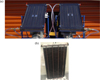 |
Fig. 1 Pictures of the solar collectors. |
Specifications of the flat-plate collector.
 |
Fig. 2 Schematic diagram of the experimental setup. |
3 Experimental results
3.1 Determination of the solar collector efficiency
In order to determine the solar collector performance, we perform a calculation of the instantaneous efficiency, which is defined as the ratio of the useful energy to the total radiant incident on the collector surface. Thus,
 (1)
(1)
The useful energy extracted from the solar collector and transmitted to the fluid can be calculated from the measurement of the inlet Tin and outlet Tout bulk temperatures of the working fluid:
 (2)
where
(2)
where  is the mass flow rate of the working fluid in the solar collector, which varies from 0.01 to 0.1 kg/s, and Cp is the specific heat.
The radiant heat flux is given by
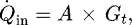 (3)
where A is the effective surface of the solar collector and Gt is the global solar radiation measured by the solar meter.
(3)
where A is the effective surface of the solar collector and Gt is the global solar radiation measured by the solar meter.
3.3 Influence of the thickness of the air gap between the absorber and the cover glazing
Two collectors were simultaneously tested and their instantaneous thermal efficiency compared. The tests were performed during the spring season (May). “Giordano” company provided both the collectors. One of the collectors was maintained unchanged and served as a reference. In the second collector, various modifications were made. First we changed the thickness of the air gap between the absorber and the cover glazing. The first modification was done to test higher thicknesses than the reference one. The manufacturer proceeded with the change in the thickness.
The thickness of the air gap for the reference collector was e = 20 mm. For the first experiment, we increased the thickness of the air gap and chose e = (20 + 6) mm. Thus, the collectors were called (R) for the reference one and (R + 6) for the second one. For the same flow rate of the working fluid in both collectors, and after 1 h of flowing, we measured the various temperatures and solar radiation. Figure 3 shows the global solar radiation (a) and the ambient temperature (b) for a sunny and a cloudy day. The recording was started at 11 a.m.
For the sunny day, we plotted the absorber plate temperature for both collectors in Figure 4. One can notice that the plate absorber temperature of the (R) collector is higher than the temperature of the (R + 6) collector.
Even both of the collectors were submitted to the same solar radiation, the (R + 6) absorber remains colder; this result leads to the conclusion that the heat losses for (R + 6) are more important than for (R). Indeed, as the thickness of the air gap between the absorber and the cover glazing is more important for (R + 6) than for (R), the convective heat transfer is larger for (R + 6) than for (R). It is well known that when a vertical thermal gradient is applied to a horizontal cavity, with heated bottom and cooled top, fluid remains quiescent till the Rayleigh number based on this thermal gradient and thickness of the fluid layer exceeds a threshold value, which in the case of infinite extension Rac = 1708. For inclined cavity, we have the coexistence of the horizontal and the vertical thermal gradients; in this case natural convection sets up instantaneously. Thus, we have formation of convective rolls. These rolls become unsteady when the air gap thickness is larger due to a higher Rayleigh number.
In order to investigate this effect on the collector efficiency, we plot in Figure 5 the instantaneous ratio of efficiencies of both the collectors for the sunny and cloudy days.
For the sunny and cloudy days, the average ratio between (R) and (R + 6) is always higher than unity, which means that the (R) collector is more efficient than the (R + 6), whatever be the external conditions. This result is coherent with the absorber temperature behavior. Thus, convection is more intense for (R + 6) than for (R). The question now is to determine the influence of the mass flow rate of the working fluid.
Figure 6 shows the evolution of the ratio of efficiencies for two different mass flow rates. In this case we considered the hourly averaged efficiencies. It appears from Figure 6 that whatever is the mass flow rate, the (R) collector is always more efficient than the (R + 6) collector, so the thickness (R + 6) of the air gap between the glazing cover and the absorber is not a good thickness.
Departing from this result, we perform two other series of experiments where the thicknesses were taken equal to (R + 3) and (R−3). The results are summarized on Figure 7, where we plot the ratio of efficiencies.
This figure shows that the reduction of the air gap thickness below the reference thickness (R) induces a better efficiency; indeed, the ratio is lower than unity. The average ratio is around 2, 1.35, and 0.68 for (R)/(R + 6), (R)/(R + 3), and (R)/(R−3), respectively. This means that for the smallest air gap thickness, the convective heat transfer is the lowest. This result is in agreement with our previous numerical study [33] where it was shown that the convection is more and more intense when the thickness of the air gap is increased.
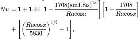
In order to confirm this result, we performed an analytical analysis based on the evaluation of the convective heat transfer. Thus, we considered the empirical correlation established by Holland et al. [28]. This later concerns the Nusselt number for inclined cavities between 0° and 60°:
 (4)
(4)
where α is the inclination angle. In our case, α = 45° and Ra is the Rayleigh number given by
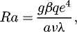 (5)where g is the acceleration gravity, β is the expansion coefficient of air, q is the heat flux absorbed by the absorber plate, e is the thickness of air gap in the cavity, a and ν are the thermal and momentum diffusivities, respectively, and λ is the thermal conductivity. This correlation shows that when the thickness e of the cavity is increased, the Nusselt number increases; thus we obtain higher convective heat transfer coefficients and consequently an increase in thermal losses of the solar collector. For a very small thickness of the air gap, conduction dominates, and heat transfer is reduced; for large thicknesses, the convection dominates. The increasing of the thickness leads to the development of the flow structure from a well-organized pattern characterized by steady longitudinal rolls to a chaotic one where the rolls are no longer identified [33]; the flow becomes turbulent and thus convective heat transfer is intensified.
The structure of the collector did not allow us to reduce the thickness below 17 mm, so we could not determine the optimum value of the thickness leading to the best efficiency; nevertheless, the obtained results show that the thickness used by the manufacturer is not adequate. So we can say that the thickness (R−3) of the air gap between the absorber plate and the cover glazing allows a better efficiency than the reference collector.
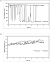 |
Fig. 3 Solar radiation (a) and ambient temperature (b) for a sunny and cloudy day. |
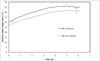 |
Fig. 4 Temperature of the plate absorber for both collectors (R) and (R + 6) for the sunny day. |
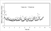 |
Fig. 5 Ratio of the efficiency of (R) upon the efficiency of (R + 6), |

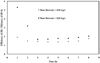 |
Fig. 6 Ratio of the hourly averaged efficiencies of (R) upon (R + 6) for two different mass flow rates. |
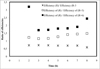 |
Fig. 7 Ratios of efficiencies for three thicknesses of the air gap for a mass flow rate |

3.4 Influence of the introduction of partitions in the air gap between the absorber and the cover glazing
The second way to reduce the convective heat transfer consists in using a honeycomb structure; however, as it was shown in the introduction [21–23], the honeycomb structure reduces the convection in the air gap and also reduces the transmittance of the solar radiation. To remedy this problem, we introduced transparent partitions in the air gap between the absorber plate and the glazing cover such that the transmittance of the solar radiation is not affected. The partitions were made of Plexiglas, their thickness is about 0.2 mm, and their height is about 18 mm. To avoid conduction, the partitions are positioned in the air gap without touching the absorber plate and the glazing cover.
First, we experiment the case of five transversal partitions placed normal to the absorber. Figure 8 shows the partitions in the air gap.
As for the air gap thickness, we tested simultaneously two collectors in the same conditions; the reference (R) corresponds to the unchanged one and the second one has been equipped with partitions and it is noted (R + TP).
In Figure 9, we plot the ratio of the hourly averaged efficiency of (R) upon (R + TP). The obtained average ratio (around 0.34) of efficiencies shows that the partitions play an important role in decreasing thermal losses by convection. This means that the plate absorber of the reference collector is colder than the (R + TP) collector. The plate absorber in the (R + TP) collector is less cooled and so thermal losses are smaller, and convection is less intense.
This interesting result leads us to increase the number of partitions. Indeed, we hoped to inhibit the natural convection by subdividing the cavity into a number of smaller cells and hence to achieve a lower heat transfer rate in the air gap. Thus, we maintained the collector (R + TP) with the five transversal partitions and we equipped the reference collector with five transversal partitions and four longitudinal partitions. Figure 10 shows the partitions in the air gap; in this case, the solar collector is noted (R + CP).
For the same flow rate of the working fluid, we tested both of the collectors (R + TP) and (R + CP) in the same conditions of solar radiation. The measurement of the inlet and outlet fluid temperatures allows determining and then plotting the efficiency of each collector. Figure 11 displays such a result. It is very clear from these curves, where the average efficiency is around 0.71 for the (R + CP) and 0.62 for (R + TP), that the crossed partitions enhance more the efficiency than the transversal partitions. The natural convection has been reduced, and the partitioning of the cavity leads to lower convective heat transfer and consequently higher efficiency of the solar collector. This result is in agreement with the numerical study of Mezrhab et al. [36], where it was found that the presence of partitions in an inclined cavity contributes to lower values of convective heat transfer.
 |
Fig. 8 Scheme of the disposition of the partitions in the air gap. |
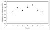 |
Fig. 9 Ratio of efficiencies of the (R) upon (R + TP) collector for a mass flow rate |

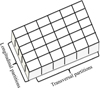 |
Fig. 10 Schematic of the partitions in the air gap between the glazing and the absorber plate for the (R + CP) collector. |
 |
Fig. 11 Hourly average efficiency of the (R + TP) and (R + CP) collectors for a fluid mass flow rate |

4 Conclusion
An experimental study of plate solar collector efficiency has been carried out. The aim of this study is to find a simple way to increase the efficiency. Natural convection in the air gap between the glazing cover and the absorber plate plays an important role in thermal losses of the solar collector. So the enhancement of the efficiency is linked to the natural convection that we have to avoid or to reduce to the minimum. In order to achieve this, we studied two different cases. The first one consists in the variation of the air gap thickness and the second one consists in partitioning the cavity.
To study the effect of the thickness of the air gap, we compared the efficiency of a reference collector with a standard thickness as given by the manufacturer and a collector on which we varied this thickness. The various experiments conducted in the same conditions for the reference collector and the varied thickness collector show that higher thicknesses than the reference one lead to the decrease of the collector efficiency. This means that higher thicknesses of the air gap contribute to the intensification of natural convection and induce larger thermal losses. The consideration of a thickness lower than the reference one provides a better efficiency than the reference one. In this case, the natural convection was really reduced. A small reduction of thickness ∼3 mm provokes an intensification of the efficiency ∼150%. This result was very interesting and was communicated to the manufacturer.
The second way to reduce natural convection consists in the introduction of very thin and transparent partitions in the cavity formed by the glazing cover and the absorber plate. First, only transversal partitions were placed and in a second time we added longitudinal partitions to the transversal to form a crossed structure. The transversal partitions lead to better efficiency than the reference collector and the crossed case further improves the efficiency. The enhancement is really effective and notable.
Author contribution statement
F.Z. Ferahta proceeds to the experimental measurements. C. Abid designed the experimental setup and proceeds to the analysis of the obtained results. The two authors jointly wrote the paper and discussed the conclusions.
Nomenclature
η: instantaneous efficiency
 :
useful heat flux (W)
:
useful heat flux (W)
 :
incident heat flux (W)
:
incident heat flux (W)
 :
mass flow rate (kg/s)
:
mass flow rate (kg/s)
Cp: working fluid thermal capacity (J/(kg K))
Tin: inlet working fluid temperature (K)
Tout: outlet working fluid temperature (K)
A: surface of the solar collector (m2)
Gt: global solar radiation (W/m2)
e: thickness of the air gap (mm)
Nu: Nusselt number
Ra: Rayleigh number
q: heat flux (W/m2)
References
- N.R. Avezova, Appl. Sol. Energy 46, 172 (2010) [CrossRef] [Google Scholar]
- T. Essabbani, F. Moufekkir, A. Mezrhab, H. Naji, Appl. Sol. Energy 51, 22 (2015) [CrossRef] [Google Scholar]
- E.S. Abbasov, A. Umurzakova, U.ZH. Nigmatov, Appl. Sol. Energy 46, 44 (2010) [CrossRef] [Google Scholar]
- N. Madhukeshwara, E.S. Prakash, Int. J. Energy Environ. 3, 99 (2012) [Google Scholar]
- Y.R. Sekhar, K.V. Sharma, R.T. Karapparaj, ARPN J. Eng. Appl. Sci. 4, 15 (2009) [Google Scholar]
- Y.B.M. Henry, R.E. Peterson, B. Zimmer, J. Thin Solid Film 39, 95 (1976) [CrossRef] [Google Scholar]
- A.A. Rempel, N.S. Kozhevnikova, A.J.G. Leenaers, S. Vanden Berghe, J. Cryst. Growth 8, 300 (2005) [Google Scholar]
- M. Dubita, I. Isac, A. Duta, Bull. Mater Sci. 35, 997 (2012) [CrossRef] [Google Scholar]
- B. Ramadhani, J.A.M. Rwaichi, N.N. Karoli, J. Energy, 2014, 247287 (2014) [Google Scholar]
- K.S. Das, A. Chakraverty, Energy Conversion and Managment 31, 233 (1991) [CrossRef] [Google Scholar]
- F. Giovannetti, S. Föste, N. Ehrmann, G. Rockendorf, Energy Procedia 30, 106 (2012) [Google Scholar]
- A. Naiem, S.C. Mullick, Int. J. Heat Mass Transf. 15, 125 (2012) [Google Scholar]
- A. Bisen, P.P. Dass, R. Jain, MIT Int. J. Mech. Eng. 1, 71 (2011) [Google Scholar]
- A.S. Youcef, Renew. Energy 30, 271 (2005) [Google Scholar]
- N. Akhtar, S.C. Mullick, Int. J. Heat Mass Transf. 55, 125 (2012) [Google Scholar]
- S. Furbo, L. Jivan, Sol. Energy 74, 513 (2003) [Google Scholar]
- J. Manikandan, B. Sivaraman, Int. Energy J. 16, 151 (2016) [Google Scholar]
- H. Abdi, N. Ait Messaoudene, Revue des Energies Renouvelables 53 (2000) [Google Scholar]
- J.T. Zhang, C.S. Hanzhong, Sol. Energy 117, 192 (2015) [Google Scholar]
- G. Francia, Proc. UN Conf. Rome 554 (1961) [Google Scholar]
- M.N. Metwally, H.Z. Abou-Ziyan, A.M. El-Leathy, Renew. Energy 10, 519 (1997) [Google Scholar]
- K.G.T. Hollands, K. Iynkaran, Sol. Energy 343, 09 (1985) [Google Scholar]
- A.H. Abdullah, H.Z. Abou-Ziyan, A.A. Ghoneim, Energy Convers. Manag. 44, 2991 (2003) [Google Scholar]
- W.W.S. Charters, L.F. Peterson, Sol. Energy 13, 353 (1971) [Google Scholar]
- N.D. Kaushika, R. Padmapriya, M. Arulanantham, P.K. Sharma, Energy 19, 1037 (1994) [CrossRef] [Google Scholar]
- W.H. McAdams, Heat Transmission, 3rd edn (McGraw-Hill, New York, 1954) [Google Scholar]
- H. Buchberg, I. Catton, D.K. Edwards, J. Heat Transf. 98, 182 (1976) [CrossRef] [Google Scholar]
- K.G.T. Hollands, T.E. Unny, G.D. Raithby, J. Heat Transf. 98, 189 (1976) [CrossRef] [Google Scholar]
- J. Vestlund, M. Ronnelid, J.O. Dalenback, Sol. Energy 83, 896 (2009) [Google Scholar]
- N.M. Nahar, P.G. Modish, Energy Res. 13, 727 (1989) [CrossRef] [Google Scholar]
- N.M. Nahar, H.P. Garg, Appl. Energy 7, 129 (1980) [Google Scholar]
- S.N. Agbo, E.C. Okoroigwe, Res. J. Phys. 1, 35 (2007) [CrossRef] [Google Scholar]
- F.Z. Ferahta, S. Bougoul, M. Medale, C. Abid, FDMP 8, 339 (2012) [Google Scholar]
- G. Colangelo, E. Favale, P. Miglietta, A. De Risi, Renew. Sustain. Energy Rev. 57, 1141 (2016) [CrossRef] [Google Scholar]
- B. Himangshu, A. Ruhul, Energy Rep. 3, 119 (2017) [CrossRef] [Google Scholar]
- A. Mezrhab, M. Jami, C. Abid, M. Bouzid, P. Lallemand, Int. J. Heat Fluid Flow 27, 456 (2006) [Google Scholar]
Cite this article as: Fatima-Zohra Ferahta, Cherifa Abid, Intensification of a flat solar collector efficiency, Eur. Phys. J. Appl. Phys. 83, 30903 (2018)
All Tables
All Figures
|
Fig. 1 Pictures of the solar collectors. |
| In the text | |
|
Fig. 2 Schematic diagram of the experimental setup. |
| In the text | |
|
Fig. 3 Solar radiation (a) and ambient temperature (b) for a sunny and cloudy day. |
| In the text | |
|
Fig. 4 Temperature of the plate absorber for both collectors (R) and (R + 6) for the sunny day. |
| In the text | |
|
Fig. 5 Ratio of the efficiency of (R) upon the efficiency of (R + 6), |
| In the text | |
|
Fig. 6 Ratio of the hourly averaged efficiencies of (R) upon (R + 6) for two different mass flow rates. |
| In the text | |
|
Fig. 7 Ratios of efficiencies for three thicknesses of the air gap for a mass flow rate |
| In the text | |
|
Fig. 8 Scheme of the disposition of the partitions in the air gap. |
| In the text | |
|
Fig. 9 Ratio of efficiencies of the (R) upon (R + TP) collector for a mass flow rate |
| In the text | |
|
Fig. 10 Schematic of the partitions in the air gap between the glazing and the absorber plate for the (R + CP) collector. |
| In the text | |
|
Fig. 11 Hourly average efficiency of the (R + TP) and (R + CP) collectors for a fluid mass flow rate |
| In the text | |
Current usage metrics show cumulative count of Article Views (full-text article views including HTML views, PDF and ePub downloads, according to the available data) and Abstracts Views on Vision4Press platform.
Data correspond to usage on the plateform after 2015. The current usage metrics is available 48-96 hours after online publication and is updated daily on week days.
Initial download of the metrics may take a while.