| Issue |
Eur. Phys. J. Appl. Phys.
Volume 101, 2026
|
|
|---|---|---|
| Article Number | 7 | |
| Number of page(s) | 7 | |
| DOI | https://doi.org/10.1051/epjap/2026005 | |
| Published online | 24 April 2026 | |
https://doi.org/10.1051/epjap/2026005
Original Article
Selectively igniting plasmas in air at atmospheric pressure through time-reversal of microwaves
1
ONERA/DMPE, Université de Toulouse, 31055 Toulouse, France
2
LAPLACE, Université de Toulouse, CNRS, INPT, UPS, Toulouse, France
3
ISAE-SUPAERO, Université de Toulouse, France
* e-mail: This email address is being protected from spambots. You need JavaScript enabled to view it.
Received:
16
September
2025
Accepted:
27
March
2026
Published online: 24 April 2026
Abstract
Methods that could enable the generation of plasmas in air, at atmospheric pressure, and with the ability to precisely target where and when the plasmas are created are of great interest to domains such as fuel combustion. In this study, we show experimentally that this can be achieved by focusing nanosecond pulses through time reversal (TR) on split-ring resonator initiators. The choice of the TR signal determines the initiator on which the plasma is created. The role of the initiator in reaching the required gas breakdown field, the influence of the TR pulse duration and the electrical signature of the plasma on the received signal are also briefly investigated.
Key words: Time-reversal / microwave plasma breakdown / split-ring resonator / nanosecond plasma
© P. Dussolliet-Berthod et al., Published by EDP Sciences, 2026
 This is an Open Access article distributed under the terms of the Creative Commons Attribution License https://creativecommons.org/licenses/by/4.0 which permits unrestricted use, distribution, and reproduction in any medium, provided the original work is properly cited.
1 Introduction
Currently, aircraft engines rely on the combustion of an air/fuel mixture, which is ignited with a spark plug (or igniter plug). Even though this technology has been in use for a long time, mainly thanks to its robustness and cost efficiency, it exhibits multiple drawbacks. A number of them are related to its fixed position at the combustion chamber wall. First, the location where the energy is deposited cannot be changed to take into account possible modifications to the internal airflow or fuel injection. A significant amount of energy is also lost via thermal conduction through the chamber wall. These issues hinder the ignition process, with the most critical conditions being at high altitudes and low temperatures, reducing the engine operational domain. Spark plugs are also subject to fouling and electrode erosion, thus requiring maintenance and replacement. Multiple plasma technologies are currently being investigated to enhance or replace igniter plugs: laser ignition [1–3], radio-frequency [4] or nanosecond [5,6] discharges, and microwave ignition [7–9]. A technology that could also change where the plasma is created depending on the conditions encountered at the start of the engine and do so regardless of the igniter location would be even more beneficial.
Time-reversal (TR) [10,11] could be a solution by providing a way to choose where the plasmas are created, thanks to its ability to precisely focus microwaves [12] and thereby generate the high-intensity electric fields necessary to locally reach gas breakdown. In fact, the use of TR to generate plasmas has already been demonstrated in argon at pressures around 1 Torr ( ) [13,14]. This remains far from the stated goal of igniting plasmas in air at atmospheric pressure (Patm). The difficulty is related to the very high microwave breakdown threshold of air at Patm: the field intensities reached by TR so far have not been high enough to reach breakdown in these conditions.
One of the possible solutions to overcome this is to use initiators to further increase the electric field at the focus point of time-reversal. Among different types of initiators (sharp tips, small gaps between tips, resonant devices, etc.), split-ring resonators (SRRs), originally introduced in [15] for metamaterial applications, are interesting for plasma ignition due to their resonant property: when excited at the appropriate frequency, they locally increase the electric field in their gap. This increase can be on the order of one thousand [16]. In fact, this was first effectively used to generate micro-plasmas in low-pressure air (1–20 Torr) or argon (1–70 Torr) by directly feeding them [17] and then by remotely exciting them with microwaves [18] (in argon at up to Patm). Recently, it has also been shown that micro-plasmas generated in this way can be used to ignite fuel/air mixtures [16]. However, in this last experiment, the absence of focalization due to the use of simple pulsed sinusoidal signals did not allow them to choose which SRR was excited and, therefore, where the plasmas were created.
In this study, we show that by coupling both principles presented above, namely time-reversal focusing and local field enhancement with SRRs, we are able to generate plasmas at different locations, in air, at Patm, and with a single microwave source.
The article is organized as follows. First, the experimental setup and protocol are presented. Next, we present the achieved results. Finally, in the conclusion, we discuss some of the possible improvements and future research.
2 Experimental setup and method
2.1 Reverberant cavity and microwave system
In this work, the experimental setup is taken from [16]. It is mainly composed of three parts: a reverberant electromagnetic cavity, a microwave system, and initiator/antenna pairs inside the cavity. The cavity is of large dimensions (2 × 1 × 1 m), with copper walls to reduce losses and features a shielded window to see inside (see [16] for more details on the design). It is not airtight, and the gas inside is therefore air at atmospheric pressure. The microwave feeding system is made up of a Tektronix AWG70001 arbitrary waveform generator (AWG), a power amplifier (TMD PTC7353, peak power rating of 3kW), and an antenna to inject the signals into the cavity. In addition, a circulator and a bi-directional coupler are used to respectively protect the amplifier against potential reflections at the cavity entrance and measure the forward and reflected signals. On the receiver side, an oscilloscope (Keysight DSO91304A) is used to record the signals received on the antennas inside the cavity. See Figure 1a for a simplified schematic of the experimental setup.
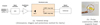 |
Fig. 1 Experimental setup. |
2.2 Split-ring resonators
To facilitate the ignition of the plasma, split-ring resonator initiators made of copper were used. Their dimensions (diameter = 10 mm, width = 1 mm, height = 1 mm, and gap = 200 μm) were chosen to obtain a resonant frequency of approximately 4 GHz [19]. This frequency was chosen for two reasons: (a) to decrease the size of the focal spot compared to previous experiments conducted at 2.5 GHz [13] (its diameter is proportional to λ/2), and therefore increase the power density at the focus, and (b) to use the amplifier at the frequency where its output power is maximum. As for the small gap size, it was chosen to reduce the breakdown field. Two SRRs were used (Fig. 1a): both were placed near the center of the cavity, out of convenience, although other locations could have been used. More precisely, the SRR 2 was directly above the SRR 3, with a vertical separation of 12 cm between them (approximately 3 times the focal spot, which has a theoretical diameter [11] of λ/2 = 3.75 cm).
2.3 SRR  -field probes
In order to receive the signals at the locations of the SRRs during the initial acquisition step and during the refocusing stage after time-reversal, small magnetic loops of diameter ≈20 mm with a somewhat flat unloaded frequency response around 4 GHz were used. Magnetic loops were chosen due to their sensitivity to the magnetic field, like the SRRs. To ensure that the SRRs were co-localized with the magnetic loops and had the same orientation, the SRRs were placed on small pieces of kapton tape stretched across the magnetic loops (Fig. 1b). Due to coupling between the magnetic loop and the SRR, this assembly constitutes a single “SRR  -field probe” (hereinafter referred more shortly as a “probe”), whose response is a combination of both the SRR and the magnetic loop responses.
Here, we shall also note that the resonant frequency of an SRR depends on its position and orientation relative to its associated magnetic loop due to coupling. The frequency response of the SRRs were therefore measured directly on the magnetic loops, by first determining the reflection coefficient of the loop alone (S22,∅, for the loop 2), then with the SRR (S22,SRR), and finally taking the difference:  (the procedure is identical for the other SRR/magnetic loop pair). The resonant frequency is then simply taken as the frequency for which the frequency response is maximum. As an example, Figure 2 shows the frequency response of SRR 2, its resonance being at 4.00 GHz. By carefully adjusting the position of each SRR inside its loop, the resonant frequencies of the probes were adjusted. When a difference of 20 MHz or less was reached (approximately 0.5% of the resonant frequency), the match was deemed very good and no further adjustments were made. This tight match in terms of resonant frequency is necessary to ensure that the SRRs are targeted based on the choice of the TR signal used. If the SRRs had different resonant frequencies, they could simply be addressed by changing the carrier frequency of the injected signal, as was done in previous experiments on remote plasma generation with SRRs [18].
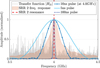 |
Fig. 2 Frequency spectra of elements of interest: Transfer function |H21| (in gray), each peak corresponds to a mode; SRR frequency response (orange area); SRR resonance (dashed red line); typical pulse used in this study (dark blue, with markers) and longer and shorter pulses (blue lines). |
2.4 Experimental protocol
The experimental protocol is the following. First, the transfer functions H21 and H31 between antenna 1 and the probes are measured with a Keysight E5071C Vector Network Analyzer (VNA). Once the target and experimental parameters are chosen (duration of the desired TR pulse, pulse carrier frequency, etc.), the TR signal  to focus on target i can be computed via :
  , with P(f) the chosen pulse and X(f)* the complex conjugate of X(f). Next,
  is converted to the time domain via an inverse Fourier transform. The time domain signal
  is then emitted by the AWG, amplified and injected into the cavity. The signals on both probes after time-reversal are then recorded with an oscilloscope. Finally, the presence or the absence of a plasma in the gap of the targeted SRR (and the other one) is determined by the visible light it emits and its signature on the received signal (see later on).
3 Results
To ignite plasmas in the gap of the SRRs, as well as to verify the spatio-temporal re-focalization on our experimental setup, two TR signals were generated :  to focus on probe 2 and
  to focus on probe 3. More precisely, for this experiment we used pulses of duration 10 ns (this corresponds to a bandwidth of approximately 400 MHz) with a carrier frequency of fc = 4 GHz (around the resonant frequency of the SRR) for both targets. This pulse duration, or equivalently, bandwidth, was chosen to exploit a large number of resonant modes of the cavity (visible on the transfer function |H21| between antenna 1 and probe 2), and therefore achieve a good spatio-temporal focalization, while the main part of the amplifier power remains in the resonance bandwidth of the SRR (Fig. 2). Due to a limitation on the power amplifier maximum duty cycle (5%), the duration of the TR signals was 10 μs and they were emitted every 200 μs. The two TR signals
  and
and  are shown in Figure 3a. After generation by the AWG, the TR signals were amplified by around 74 dB, resulting in output peak powers of approximately 3 kW, and injected into the cavity. This resulted in approximately 2 mJ of energy being injected in the cavity during each amplification window (estimation based on the integration of the output signal measured through the bidirectional coupler). These experiments were conducted with air at atmospheric pressure inside the cavity to show the ability of time-reversal to ignite a plasma in these conditions.
After emission and propagation of the waves in the reverberant cavity, the resulting signals on probes 2 and 3 were recorded with an oscilloscope. As shown in the second row of Figure 3, spatio-temporal focalization through time-reversal is achieved. Indeed, when the TR signal generated to target probe 2 is emitted (Fig. 3a), only noise is observed on 3, while a short pulse of comparatively high amplitude is observed on probe 2 (Fig. 3b). Conversely, when probe 3 is targeted, a TR pulse is observed on 3 and only noise is present on 2, as expected (Fig. 3b).
Now looking through the shielded window, a small plasma can be seen in the gap of the SRR of probe 2 when it is targeted, whereas no plasma is visible on SRR of probe 3, as evidenced by Figure 3c. A close-up view of the plasma on probe 2 can be seen on Figure 4. Similarly, a plasma is only visible on the SRR of probe 3 when it is targeted (Fig. 3c). These results show the ability to select on which SRR the plasma is ignited, and that a plasma can be generated with only one high power TR pulse of 10 ns in air at atmospheric pressure. Spread over a few days and the two probes, plasmas were ignited more than a dozen times in such a way. This is an improvement over previous experiments conducted on this setup where the location of the plasmas could not be chosen due to the use of simple sinusoidal signals [16].
Looking at the received signal more closely, a potential signature of the plasma can be detected, as evidenced in Figure 5. At the high power setting (Fig. 5a), when a plasma is visible, a small dip in the signal can be seen (indicated by the black arrow). For example, in this series of measurements, the signal decreased by 84 ± 26 mV (approx. 48% decrease), starting at 10.0472 μs ± 0.3 ns and reaching a minimum at 10.0475 μs ± 0.4 ns (average over 5 successive TR peaks). When the same signal is sent at a power level below the plasma ignition threshold, this temporary decrease in the signal is absent (Fig. 5b). Although not shown, this dip in the received signal was observed when a plasma was also visible in all further experiments conducted in this study, hence the name “plasma signature”. A combination of three phenomena can explain the decrease in the received signal: (a) absorption of some of the power by the plasma, (b) a change in the SRR resonant frequency due to the plasma in its gap (detuning) [20], and (c) a redistribution of the modes in the cavity due to the presence of the plasma. Further work would be necessary to determine which of the three phenomena is predominant.
The next experiment was to determine whether the resonance of the SRR plays a role in the formation of the plasma: this was done by injecting TR signals with different carrier frequencies and evaluating the effect on plasma ignition. For this experiment, TR signals for the probe 2 only, the most visible from the window, with carrier frequencies ranging from 3.5 to 4.5 GHz were generated, while the other signal parameters remained unchanged (pulse of 10 ns, etc.). In order to minimize a potential “memory effect” due to left-over free electrons, an arbitrary waiting time of 2 min was chosen between each test. This experiment was conducted a first time (one test for each frequency) and repeated the next day; the results were identical. The results of the frequency sweep are shown in Figure 6, with each symbol indicating if a plasma appeared at that carrier frequency or not. They show that the resonant property of the SRR indeed plays a role in plasma ignition here, since no plasma was created outside of the SRR resonance. We shall also note that the “dip” in the signal mentioned previously was only observed at frequencies where a plasma was present, confirming that it is a “plasma signature”.
Finally, we investigated the effect of the TR pulse duration on plasma ignition. For this purpose, TR signals with pulse durations ranging from 5 to 200 ns were generated, while the carrier frequency was kept at 4.0 GHz and the other parameters remained unchanged. Each duration was tested twice on two different days. The results are reported in Table 1.
First, we note that pulses of 10 and 20 ns are able to reliably ignite a plasma (all tests successful). On the other hand, when much longer pulse durations were used (100 and 200 ns), no plasma could be observed. As shown in Figure 2, these longer pulses have a narrower bandwidth (only 40 MHz for pulses of 100 ns versus 400 MHz for a pulse of 10 ns, see Fig. 2). This results in a degradation of the focalization (since less modes are used), lower TR peak amplitudes, and might explain the absence of plasma ignition. For very short pulses of 5 ns, plasma ignition is also unreliable (no plasma during half of the tests). A first explanation is that the bandwidth of the pulse is too large relative to the SRR resonance, and only a small amount of energy is effectively used by the SRR (Fig. 2). Another explanation is that, while shorter pulse durations improve focusing and increase the TR peak amplitude, they also require higher field strengths to trigger breakdown, as highlighted in [21].
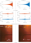 |
Fig. 3 Experimental results. |
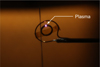 |
Fig. 4 Close-up picture of the plasma on probe 2. (Note: The picture was taken from the opposite side of the cavity compared with Figure 3, which explains why the probe is mirrored). |
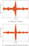 |
Fig. 5 Signal measured by probe 2 after focusing (TR pulse carrier frequency of 4 GHz). |
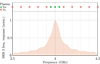 |
Fig. 6 Plasma ignition as a function of the TR pulse carrier frequency (on probe 2). |
Plasma ignition versus TR pulse duration. (Legend: ✓ plasma ignition, × no plasma, ∼ unreliable plasma ignition).
4 Conclusion
In conclusion, we demonstrated, for the first time to our knowledge, the ability of time-reversal of microwaves to generate plasmas in air at atmospheric pressure. This was done thanks to the use of 10 to 20 ns pulses that enabled us to precisely target which magnetic loop/SRR pair to focus the microwaves on. In doing so, we exploited the resonant property of SRRs, which allowed us to reach higher electric field intensities than possible with TR alone. This was evidenced by changing the TR signal carrier frequency, showing that no plasma appeared outside of the SRR resonance. The presence of the plasma was confirmed both by the light it emitted and the detection of a signature on the received signal. We also observed that the TR pulse duration impacted the plasma ignition process.
Further work could focus on determining the limits of this method (minimum pulse duration and power, spatial resolution, etc.), characterizing the resulting plasma (spectroscopy, etc.) and investigating the dynamics of breakdown by using a high-speed camera. We also plan to conduct fuel ignition experiments and verify that plasmas can be generated by TR in a setup that is more representative of a real combustor (lower Q-factor, different geometry, etc.). Both of these experiments will help to evaluate the prospects of this method as a potential spark plug replacement.
Acknowledgments
We would like to thank CEA Gramat for lending us a power amplifier.
Funding
The work presented here was funded by the Agence de l’Innovation de Défense (AID) and ONERA.
Conflicts of interest
The authors have nothing to disclose.
Data availability statement
The data that support the findings of this study are available from the corresponding author upon reasonable request.
Author contribution statement
Pierre Dussolliet-Berthod: Conceptualization (equal); Investigation (equal); Methodology (equal); Software (lead); Validation (equal); Visualization (lead); Writing—original draft (lead); Writing—review & editing (equal).
Benjamin Fromont: Conceptualization (supporting); Investigation (equal); Methodology (equal); Validation (equal); Writing—review & editing (equal).
Jérôme Sokoloff: Conceptualization (equal); Funding acquisition (equal); Methodology (equal); Resources (equal); Supervision (equal); Writing—review & editing (equal).
Olivier Pascal: Conceptualization (equal); Funding acquisition (equal); Methodology (equal); Resources (equal); Supervision (equal); Writing—review & editing (equal).
Olivier Rouzaud: Conceptualization (equal); Funding acquisition (equal); Methodology (equal); Resources (equal); Supervision (equal); Writing—review & editing (equal).
Mikael Orain: Conceptualization (supporting); Funding acquisition (equal); Resources (equal); Supervision (supporting); Writing—review & editing (equal).
Valentin Mazières: Conceptualization (supporting); Writing—review & editing (equal).
All the authors were involved in the preparation of the manuscript. All the authors have read and approved the final manuscript.
References
- B. Done, Experimental investigations of LASER ignition use at spark ignition engine, Procedia Manuf. 22, 659 (2018). https://doi.org/10.1016/j.promfg.2018.03.095 [CrossRef] [Google Scholar]
- S.A. O’Briant, S.B. Gupta, S.S. Vasu, Review: Laser ignition for aerospace propulsion, Propuls. Power Res. 5, 1 (2016). https://doi.org/10.1016/j.jppr.2016.01.004 [CrossRef] [Google Scholar]
- M. Maillard et al., Ignition of a Safran’s helicopter engine with a compact nanosecond laser system, in: ASME Turbo Expo 2023: Turbomachinery Technical Conference and Exposition (American Society of Mechanical Engineers Digital Collection, 2023). https://doi.org/10.1115/GT2023-103897 [Google Scholar]
- A. Starikovskiy, N. Aleksandrov, Plasma-assisted ignition and combustion, Prog. Energy Combust. Sci. 39, 61 (2013). https://doi.org/10.1016/j.pecs.2012.05.003 [Google Scholar]
- S. Bentaleb, P. Tardiveau, F. Jorand, P. Jeanney, L. Magne, Ignition of N2/O2/C3H8 mixtures by a single nanosecond pulsed discharge at atmospheric pressure, in: 20th International Symposium on Plasma Chemistry (2011) [Google Scholar]
- S. Lovascio, J. Hayashi, S. Stepanyan, G.D. Stancu, C.O. Laux, Cumulative effect of successive nanosecond repetitively pulsed discharges on the ignition of lean mixtures, Proc. Combust. Instit. 37, 5553 (2019). https://doi.org/10.1016/j.proci.2018.06.029 [Google Scholar]
- A.M. Davydov, S.I. Gritsinin, I.A. Kossyi, Y.M. Shikhman, V.A. Vinogradov, Application of MW plasma generator for ignition of kerosene/air mixture, IEEE Trans. Plasma Sci. 36, 2909 (2008). https://doi.org/10.1109/TPS.2008.2006977 [CrossRef] [Google Scholar]
- M.K. Le, A. Nishiyama, Y. Ikeda, Evaluation of a novel miniaturised microwave resonating igniter: the flat panel igniter, Proc. Combust. Instit. 37, 5613 (2019). https://doi.org/10.1016/j.proci.2018.06.024 [Google Scholar]
- B. Fragge, J. Sokoloff, O. Rouzaud, O. Pascal, M. Orain, A versatile set-up to study plasma/microwave sources for liquid fuel ignition, Eur. Phys. J. Appl. Phys. 92, 30903 (2020). https://doi.org/10.1051/epjap/2020200228 [Google Scholar]
- M. Fink, C. Prada, F. Wu, D. Cassereau, Self focusing in inhomogeneous media with time reversal acoustic mirrors, Proc. IEEE Ultrason. Symp. 2, 681 (1989). https://doi.org/10.1109/ULTSYM.1989.67072 [Google Scholar]
- C. Draeger, M. Fink, One-channel time reversal of elastic waves in a chaotic 2D-silicon cavity, Phys. Rev. Lett. 79, 407 (1997). https://doi.org/10.1103/PhysRevLett.79.407 [Google Scholar]
- G. Lerosey, J. Rosny, A. Tourin, D. Arnaud, G. Montaldo, M. Fink, Time reversal of electromagnetic waves, Phys. Rev. Lett. 92, 193904 (2004). https://doi.org/10.1103/Phys-RevLett.92.193904 [Google Scholar]
- V. Mazières, R. Pascaud, L. Liard, S. Dap, R. Clergereaux, O. Pascal, Plasma generation using time reversal of microwaves, Appl. Phys. Lett. 115, 154101 (2019). https://doi.org/10.1063/1.5126198 [CrossRef] [Google Scholar]
- V. Mazières, R. Pascaud, O. Pascal, R. Clergereaux, L. Stafford, S. Dap, L. Liard, Spatio-temporal dynamics of a nanosecond pulsed microwave plasma ignited by time reversal, Plasma Sources Sci. Technol. 29, 125017 (2020). https://doi.org/10.1088/1361-6595/abc9ff [Google Scholar]
- J.B. Pendry, A.J. Holden, D.J. Robbins, W.J. Stewart, Magnetism from conductors and enhanced nonlinear phenomena, IEEE Trans. Microw. Theory Tech. 47, 2075 (1999). https://doi.org/10.1109/22.798002. [CrossRef] [Google Scholar]
- B. Fragge, J. Sokoloff, O. Rouzaud, O. Pascal, M. Orain, Fuel ignition using remote generation of microwave plasma in air at atmospheric pressure, Eur. Phys. J. Appl. Phys. 99, 2 (2024). https://doi.org/10.1051/epjap/2023230152. [Google Scholar]
- F. Iza, J.A. Hopwood, Low-power microwave plasma source based on a microstrip split-ring resonator, IEEE Trans. Plasma Sci. 31, 782 (2003). https://doi.org/10.1109/TPS.2003.815470 [CrossRef] [Google Scholar]
- P.K. Singh, J. Hopwood, S. Sonkusale, Metamaterials for remote generation of spatially controllable two dimensional array of microplasma, Sci. Rep. 4, 5964 (2014). https://doi.org/10.1038/srep05964 [Google Scholar]
- O. Sydoruk, E. Tatartschuk, E. Shamonina, L. Solymar, Analytical formulation for the resonant frequency of split rings, J. Appl. Phys. 105, 014903 (2009). https://doi.org/10.1063/1.3056052 [CrossRef] [Google Scholar]
- F. Iza, J. Hopwood, Split-ring resonator microplasma: microwave model, plasma impedance and power efficiency, Plasma Sources Sci. Technol. 14, 397 (2009). https://doi.org/10.1088/0963-0252/14/2/023 [Google Scholar]
- V. Mazières, O. Pascal, R. Pascaud, L. Liard, S. Dap, R. Clergereaux, J.-P. Boeuf, Space-time plasma-steering source: control of microwave plasmas in overmoded cavities, Phys. Rev. Appl. 16, 054038 (2021). https://doi.org/10.1103/PhysRevApplied.16.054038 [Google Scholar]
Cite this article as: Pierre Dussolliet-Berthod, Benjamin Fromont, Jérôme Sokoloff, Olivier Rouzaud, Olivier Pascal, Mikael Orain, Valentin Mazières, Selectively igniting plasmas in air at atmospheric pressure through time-reversal of microwaves, Eur. Phys. J. Appl. Phys. 101, 7 (2026) https://doi.org/10.1051/epjap/2026005
All Tables
Plasma ignition versus TR pulse duration. (Legend: ✓ plasma ignition, × no plasma, ∼ unreliable plasma ignition).
All Figures
|
Fig. 1 Experimental setup. |
| In the text | |
|
Fig. 2 Frequency spectra of elements of interest: Transfer function |H21| (in gray), each peak corresponds to a mode; SRR frequency response (orange area); SRR resonance (dashed red line); typical pulse used in this study (dark blue, with markers) and longer and shorter pulses (blue lines). |
| In the text | |
|
Fig. 3 Experimental results. |
| In the text | |
|
Fig. 4 Close-up picture of the plasma on probe 2. (Note: The picture was taken from the opposite side of the cavity compared with Figure 3, which explains why the probe is mirrored). |
| In the text | |
|
Fig. 5 Signal measured by probe 2 after focusing (TR pulse carrier frequency of 4 GHz). |
| In the text | |
|
Fig. 6 Plasma ignition as a function of the TR pulse carrier frequency (on probe 2). |
| In the text | |
Current usage metrics show cumulative count of Article Views (full-text article views including HTML views, PDF and ePub downloads, according to the available data) and Abstracts Views on Vision4Press platform.
Data correspond to usage on the plateform after 2015. The current usage metrics is available 48-96 hours after online publication and is updated daily on week days.
Initial download of the metrics may take a while.