| Issue |
Eur. Phys. J. Appl. Phys.
Volume 97, 2022
Special issue on ‘Thermal and magnetic studies for efficient electrical machines’, edited by Jean-Philippe Lecointe, Lionel Pichon, Paolo Di Barba and Krzysztof Komeza
|
|
|---|---|---|
| Article Number | 68 | |
| Number of page(s) | 8 | |
| Section | Physics of Energy Transfer, Conversion and Storage | |
| DOI | https://doi.org/10.1051/epjap/2022220007 | |
| Published online | 27 September 2022 | |
https://doi.org/10.1051/epjap/2022220007
Regular Article
2D hybrid magneto-thermal model for PM induction heating device with rotating movement
1
LSEI-Université des Sciences et de la Technologie Houari Boumediene, BP N°32, 16111 Alger, Algeria
2
GREAH, EA3220, Université Le Havre Normandie, 76600 Le Havre, France
* e-mail: This email address is being protected from spambots. You need JavaScript enabled to view it.
Received:
12
January
2022
Received in final form:
1
April
2022
Accepted:
5
May
2022
Published online: 27 September 2022
Abstract
A new 2D-hybrid model in cylindrical coordinates intended for the study of a transient magneto-thermal coupled problem is proposed. This model is used to evaluate the spatiotemporal distribution of temperature in rotating aluminum billets heated by permanent magnets induction-heating device (PMIHD). The proposed hybrid model consists of coupling an exact analytical solution of the 2D magneto-harmonic field to a 2D transient thermal analysis where the temperature dependence of electrical and thermal physical properties of the heated billet is considered. Based on the separation variables technique, the analytical solution of magneto-harmonic problem serves to evaluate the induced current and the resulting power density loss distribution in the nonmagnetic billet. Furthermore, the 2D transient thermal analysis, based on the lumped thermal network model, is developed in radial and axial directions of the heated billet. In order to validate the 2D hybrid magneto-thermal model, the performances of the studied PMIHD are compared with those obtained with Finite Element Method (FEM).
© B. Meriem et al., Published by EDP Sciences, 2022
 This is an Open Access article distributed under the terms of the Creative Commons Attribution License (http://creativecommons.org/licenses/by/4.0), which permits unrestricted use, distribution, and reproduction in any medium, provided the original work is properly cited.
1 Introduction
Aluminum profiles are widely used products in today’s world. For the manufacturing of these products, electromagnetic induction heaters are used at aluminum plants to preheat aluminum cylinders, so called billets, before extruded to profiles. In these plants, typical billets having 200 mm diameter and 1000 mm height are heated up to a temperature level between 400 °C and 500 °C (depends on extrusion process) in order to soften the metal before it is pressed through the extruder. It is important to reach a temperature distribution as uniform as possible in the billet, for the quality of the forming process [1].
Electromagnetic induction heating is a fast and clean possibility to heat. The process can be controlled precisely and reproducible. Since energy costs are growing, efficiency of heating processes becomes a more and more important issue. Heating of nonmagnetic metals with low electrical resistivity like aluminum is connected with a low efficiency which is about 50%, if done in conventional way [2,3]. In order to save energy, a new approach to improve the efficiency is to generate a DC magnetic field by using an inductor based on modern permanent magnets. The electromagnetic field is applied in that manner that by rotation of the billet or the inductor, currents are induced in the workpiece. Due to Joule losses, the billet is heated up. A static magnetic field is generated without losses by permanent magnets, so that the efficiency of the system is determined by the efficiency of the main drive rotating the billet or the inductor. An efficiency of 85% is estimated for the process [4].
This work proposes to analyze the device of induction heating of nonmagnetic conductive billet illustrated in Figure 1. In this structure, the inductor is based on permanent magnets (Nd-Fe-B) with radial magnetization, bonded to the inner surface of a ferromagnetic yoke. In this topology, aluminum billet to be heated is placed inside the static magnetic field created by permanent magnets. The rotational movement of the billet by using a mechanical drive system produces the eddy currents and the heat power losses in the billet. However, physical models are needed for the design and analysis of these heaters, which consists to establish a mathematical formulation describing both electromagnetic and thermal phenomena. So, in this work, a new coupling way between these two phenomena is proposed. First, an exact 2D analytical solution of the electromagnetic field is derived from Maxwell equations in time harmonic formulation thanks to the separation of variables method. The resulting electromagnetic field is then used to calculate the heat power density, which represents the source of thermal model. Then, the magneto-thermal problem is obtained by coupling the developed magnetic model to a 2D transient thermal model based on the lumped thermal network model taking into account the temperature dependence of electrical and thermal physical properties of the heated billet. The results issued from the developed models are compared with those obtained by finite element method. The principal physical and geometrical parameters of the studied heater are given in Table 1.
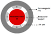 |
Fig. 1 2D induction heater geometry. |
Geometrical and physical parameters of the device.
2 2D electromagnetic analytical model
Using Maxwell’s equations in term of the magnetic vector potential  and considering that the permanent magnets inductor is fixed and the billet is suggested to a rotational movement with constant speed Ω, the electromagnetic behavior of the studied device is governed by:
 (1)
(1)
where  represents the tangential velocity of the billet, related to the angular speed by:
 (2)
(2)
For a 2D formulation, the analytical resolution of (1) can be derived by considering the following assumptions:
the device is considered with infinite length, and then the axial edge effects are neglected.
the permeability of the iron yoke is large enough to be considered as infinite (the saturation is not considered).
The polar coordinates (r,θ) are appropriate to this study, according to the geometry of the device. So, (1) is rewritten as:
 (3)
(3)
where M r denotes the radial component of the magnets magnetization and A(r,θ) is the axial magnetic vector potential component.
To solve (3), an analytical method based on the separation variables technique is applied [5].
2.1 Analytical solution of electromagnetic problem
Under the assumptions cited previously, the study area in polar coordinates (r,θ) is reduced to three regions, as shown in Figure 2 and (3) becomes:
-
region (1): nonmagnetic conductive billet (0 ≤ r ≤ R1)
 (4)
(4) -
region (2): air gap (R1 ≤ r ≤ R2)
 (5)
(5) -
region (3): permanent magnets (R2 ≤ r ≤ R3)
 (6)
(6)
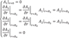
The following boundary and interface conditions must be added to the above equations:
In region (2), the permanent magnets magnetization constituting the field source is expressed by its Fourier series expansion [6,7] given by:
 (8)
(8)
where p is the pole pair number, M n is the magnitude of the nth harmonic given by:
 (9)
(9)
In (9), Β is the opening angle of the permanent magnets.
In the complex representation and using the separation variables technique, the general solution form of the vector potential, in each region, can be written as:
 (10)
(10)
where j 2 = −1 denotes the complex number.
By injecting (10) in (4), (5) and (6) respectively the corresponding  of (10) is then given as:
-
region (1):
 (11)
(11)with:
 (12)
(12)and
 is the Bessel function of the first kind and npth order.
 -
region (2):
 (13)
(13) -
region (3):
 (14)
(14)
 (15)
(15)
The integration constants  ,
,  ,
,  ,
,  and
and  are calculated by using the interface and boundary conditions (7).
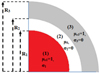 |
Fig. 2 Geometrical model of the electromagnetic problem. |
2.2 Induced current density and power heating expressions
The current density induced in the billet (region 1) by the rotation movement, is given by:
 (16)
(16)
By considering (3), (10) and (11), the complex form of the current density (16) can be written as:
 (17)
(17)
For the nth harmonic  is given by:
 (18)
(18)
The corresponding thermal source allowing to heat the billet is the induced power density, and is related to the induced currents by [5]:
 (19)
(19)
Hence, the analytical expression of the power heating density can be obtained by the following relation:
 (20)
(20)
An other important characteristic of the studied heater device is the corresponding total heating power in the billet. It is determined by integration of (20) over the billet volume:
 (21)
(21)
After integration, the final expression is:
where  and
and  ;
;  and
and 

3 2D thermal transient model
The spatiotemporal distribution of temperature inside the conductive billet is governed by the following partial differential equation [8,9]:
 (23)
(23)
representing the transient heat diffusion equation, which is solved by using the equivalent lumped thermal network model [10–12].
The thermal source,  , representing the power density induced in the billet given by (20) is the term allowing coupling the both electromagnetic and thermal problems. By considering a weak coupling between the two models, the electrical and thermal properties of the billet are updated for each variation of the temperature. In this analysis, the variation of these physical properties as a function of the temperature, is given by the following expressions:
-
for electrical conductivity:
 (24)
(24)where
 is the conductivity at T
0 (°C),
is the conductivity at T
0 (°C),  is the temperature coefficient relative to electrical conductivity.
 -
for thermal conductivity:
 (25)
(25)
where L
0 = 2.45 * 10−8 is the constant of Lorentz and  is the electrical conductivity.
In this model, the heat transfer by conduction is considered in the radial and axial (r, z) directions.
Applied to the studied PMIHD, the proposed thermal modeling method consists in establishing a lumped thermal network where the thermal limits problem comes down only to the billet to be heated and the air layer separating the billet and the inductor. This air layer is represented in the thermal model by a convective thermal resistance [13–15].
The discretization of the studied geometry in the two directions leads to elementary volumes of cylindrical shapes, that are considered as thermal nodes. The equation of the heat exchanges between the nodes gives a set of differential equations in matrix form. For each node, the associated heat transfer equations are in the form :
 (26)
(26)
where  ,
,  ,
,  ,
,  and n characterising the block ‘i’ are respectively the mass density, the elementary volume, the specific heat, the heat source and the number of nodes linked to this block.
3.1 Lumped thermal network of an elementary block
Figure 3 shows the geometrical dimensions and considered boundary conditions of a hollow cylinder having a uniform volumic heat source p 1 and a thermal conductivity λ.
For a study in the (r, z) plane, one considers that:
the temperature is invariant as a function of the angle θ; hence the heat flow presents two components: axial and radial.
the block has the same average temperature in the axial and radial directions.
the thermal conductivity in the axial and radial directions is the same (isotropic).
In steady state, the heat transfer equation in this block is derived in cylindrical coordinates from (23):
 (27)
(27)
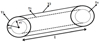 |
Fig. 3 Bidirectional block. |
3.1.1 Lumped thermal network of an elementary block in the axial direction
The lumped thermal network in the axial direction of each block element is obtained by solving (27) analytically only in the axial direction. Its solution is given by:
 (28)
(28)
The average temperature is given by:
 (29)
(29)
where  and
and  represent respectively the heat source and the block axial resistance.
The translation of (29), in the form of a network, makes it possible to represent the block by the networks of Figure 4 where  and
and  .
.
In the case where the geometry presents a symmetry, so that the temperature field is symmetrical compared to the median plane (T
3 = T
4), the previous lumped thermal network is simplified (Fig. 5) to a single resistance  .
.
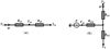 |
Fig. 4 Equivalent lumped thermal network in the axial direction: (a) |


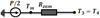 |
Fig. 5 Equivalent thermal network considering symmetry. |
3.1.2 Lumped thermal network of an elementary block in the radial direction
In the radial direction the lumped thermal network of each block element is obtained analytically by solving (27) in the radial direction. Its solution is given by:
 (30)
(30)
with α and β are constants determined as a function of the temperature imposed on the boundaries. The average temperature at the center of the block is given by:
 (31)
(31)
with:


and
The corresponding thermal networks to model the block radially are given in Figure 6 for the two cases, with and without sources.
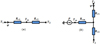 |
Fig. 6 Equivalent lumped thermal networkin the radial direction: (a) |


3.2 Lumped thermal network of the overall elementary block
The correspending thermal network of the block is obtained by combining the two radial and axial thermal networks with symmetry along z as shown in Figure 7.
The change in temperature over time (transient mode) is taken into account by defining a thermal capacity connected to the central node. It is evaluated by the relation:
 (32)
(32)
If the cylinder is full, it is enough to put:
 (33)
(33)
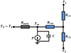 |
Fig. 7 Equivalent thermal network of elementary block with symmetry. |
3.3 Global thermal network
The global thermal network is obtained by connecting all elementary networks through the nodes of connection. The border nodes are connected to the air gap through convection thermal resistances, R cz and R cr respectively in the axial and radial directions. These convection resistances are given by:
 (34)
(34)
where S is the exchange surface and h is the thermal convective coefficient.
For a discretization of one block along z and n blocks along r the equivalent thermal network of the heating billet is represented in Figure 8 and the correspending differential equation (26) for the n radial nodes leads to, in matrix form:
 (35)
(35)
 diagonal thermal capacity matrix of
  ;
;  thermal conductances matrix of
  ;
;  thermal conductances matrix of
  ;
;  matrix transposed from
 ;
;  thermal conductances matrix of
  ;
;  average temperature vector;
  temperature vector of connecting nodes;
  heat sources vector;
  vector containing the terms T
0 for the connecting nodes; T
0 is the initial temperature of billet (T
0 = 30 °C).
vector containing the terms T
0 for the connecting nodes; T
0 is the initial temperature of billet (T
0 = 30 °C).
One note, that the heat sources are evaluated using the analytical expression of the power, obtained by the electromagnetic model developed previously.
Finally the differential equation system obtained from (35) is then:
 (36)
(36)
with:
 (37)
(37)
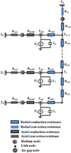 |
Fig. 8 Global equivalent thermal network (n blocks along r and one block along z). |
4 Results of the 2D hybrid magneto-thermal problem
The electromagnetic quantities obtained with the developed analytical model are shown in Figures 9 and 10. The eddy current density induced in the aluminum billet by movement is illustrated in Figure 9 at 1500 rpm. So, the corresponding total power heat induced in the billet versus angular speed is shown in Figure 10. Obviously, as shown by the analytical expression (22) and Figure 10, the total heating power is directly related to the square of the speed. Indeed, the total heating power is higher all the more so as the speed is higher. One note that the total power heat obtained at 1500 rpm is about 850 W.
The transient temperature obtained by the lumped thermal network model at the billet surface at 1500 rpm is shown in Figure 11 for one block in the axial direction and n = 54 blocks in the radial directions.
In metallurgical industry, the extrusion or shaping of conductive billets requires that they be heated to temperature levels of 400–500 °C. The heating time required to ensure good productivity of the heating device is of the order of a hundred seconds. So, one can see from these results, that the required heating levels are reached after 450’s (either 8 min) for Ω = 1500 rpm.
The results obtained by this 2D hybrid magneto-thermal model are in good agreement with those obtained by the 2D finite element method.
Figure 12 illustrates the temperature distribution in the radial direction obtained by the lumped thermal network model at a rotation speed of 1500 rpm and for a heating time of 450’s. It is observed from this figure that the temperature of the block located in the centre of the billet is T m = 411.3 °C and the temperature of the block in its surface is T m = 413.7 °C; The correspending difference is ΔT m = 2.4 °C (0.58%).
In practice, the forming operation can only be successful if the temperature profile through the volume of the billet is as homogeneous as possible. A temperature uniformity between 2.5% and 5% is required. In this case, one can then conclude that the temperature profile obtained through the volume of the billet is homogeneous.
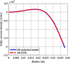 |
Fig. 9 Current density induced in billet vs r(Ω = 1500 rpm, θ = 0°). |
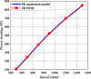 |
Fig. 10 Total power heat induced in billet vs. rotational speed. |
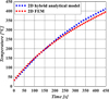 |
Fig. 11 Temperature evolution at the surface of the billet (r = 38 mm, Ω = 1500 rpm). |
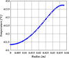 |
Fig. 12 Temperature evolution in billet vs r (θ = 0°, Ω = 1500 rpm, t = 450 s). |
5 Conclusion
2D hybrid model with new appraoch to the magneto-thermal coupling problems was developed in this work. This model was applied to a permanent magnet induction heating device of aluminum billet, which combines the static magnetic field with the rotational movement at constant speed. The magnetic and thermal results, obtained using the developed models are in good agreement with those obtained by the finite element method.
The obtained spatiotemporal distribution of the temperature in the billet shows that a homogeneous temperature profile can be reached with this induction heating device.
As a consequence, the proposed new 2D hybrid model can potentially be used to speed up magneto-thermal design of this type of induction heating devices.
Author contribution statement
Meriem Boubezari, Youcef Ouazir and Ammar Abdi: lumped parameter thermal model, programming and numerical simulation, and writing a part of the manuscript. Georges Barakat and Yacine Amara: analytical magnetic model, programming and numerical simulation, and writing a part of the manuscript. All authors contribute to the results discussion part. All authors have read and approved the final manuscript.
References
- A. Morandi, M. Fabbri, P.L. Ribani, IEEE Trans. Appl. Superconduct. 18, 816 (2008) [CrossRef] [Google Scholar]
- A. Abdi, Y. Ouazir, G. Barakat, Y. Amara, Compel 37, 1755 (2018) [CrossRef] [Google Scholar]
- H. Bensaidane, T. Lubin, S. Mezani, Y. Ouazir, A. Rezzoug, IEEE Trans. Magn. 51, 3479 (2015) [CrossRef] [Google Scholar]
- F. Mach, V. Starman, P. Karban, I. Dolezel, P. Kus, IEEE Trans. Ind. Electr. 61, 2584 (2014) [CrossRef] [Google Scholar]
- M. Markovic, Y. Perriard, IEEE Trans. Magn. 43, 3380 (2007) [CrossRef] [Google Scholar]
- M. Runde, N. Magnusson, C. Fülbier, C. Bührer, IEEE Trans. Appl. Superconduct. 21, 1379 (2011) [CrossRef] [Google Scholar]
- Z.Q. Zhu, D. Howe, E. Bolte, B. Ackermann, IEEE Trans. Magn. 29, 124 (1993) [CrossRef] [Google Scholar]
- H. Bensaidane, Y. Ouazir, T. Lubin, S. Mezani, A. Rezzoug, IEEE Trans. Appl. Superconduct. 21 , 3479 (2011) [CrossRef] [Google Scholar]
- T. Lubin, D. Netter, J. Leveque, A. Rezzoug, IEEE Trans. Magn. 45, 2118 (2009) [CrossRef] [Google Scholar]
- N. Janne, R. Marko, P. Juha, IEEE Trans. Ind. Electr. 55, 3543 (2008) [CrossRef] [Google Scholar]
- R. Hossein, F. Jawad, L. Caro, Math. Comput. Modell. 45, 625 (2007) [CrossRef] [Google Scholar]
- J. Nerg, V. Ruuskanen, Math. Comput. Simul. 90, 218 (2013) [CrossRef] [Google Scholar]
- J. Fan, C. Zhang, Z. Wang, Y. Dong, C.E. Nino, A.R. Tariq, E.G. Strangas, IEEE Trans. Magn. 46, 2493 (2010) [CrossRef] [Google Scholar]
- C.H. Lim, G. Airoldi, J.R. Bumby, R.G. Dominy, G.I. Ingram, K. Mahkamov, N.L. Brown, A. Mebarki, M. Shanel, Int. J. Therm. Sci. 49, 1732 (2010) [CrossRef] [Google Scholar]
- C. Lim, J. Bumby, R. Dominy, G. Ingram, K. Mahkamov, N. Brown, A. Mebarki, A. Shanel, Int. Conf. Electr. Mach. (2008) [Google Scholar]
Cite this article as: Boubezari Meriem, Ouazir Youcef, Abdi Ammar, Barakat Georges, Amara Yacine, 2D hybrid magneto-thermal model for PM induction heating device with rotating movement, Eur. Phys. J. Appl. Phys. 97, 68 (2022)
All Tables
All Figures
|
Fig. 1 2D induction heater geometry. |
| In the text | |
|
Fig. 2 Geometrical model of the electromagnetic problem. |
| In the text | |
|
Fig. 3 Bidirectional block. |
| In the text | |
|
Fig. 4 Equivalent lumped thermal network in the axial direction: (a) |
| In the text | |
|
Fig. 5 Equivalent thermal network considering symmetry. |
| In the text | |
|
Fig. 6 Equivalent lumped thermal networkin the radial direction: (a) |
| In the text | |
|
Fig. 7 Equivalent thermal network of elementary block with symmetry. |
| In the text | |
|
Fig. 8 Global equivalent thermal network (n blocks along r and one block along z). |
| In the text | |
|
Fig. 9 Current density induced in billet vs r(Ω = 1500 rpm, θ = 0°). |
| In the text | |
|
Fig. 10 Total power heat induced in billet vs. rotational speed. |
| In the text | |
|
Fig. 11 Temperature evolution at the surface of the billet (r = 38 mm, Ω = 1500 rpm). |
| In the text | |
|
Fig. 12 Temperature evolution in billet vs r (θ = 0°, Ω = 1500 rpm, t = 450 s). |
| In the text | |
Current usage metrics show cumulative count of Article Views (full-text article views including HTML views, PDF and ePub downloads, according to the available data) and Abstracts Views on Vision4Press platform.
Data correspond to usage on the plateform after 2015. The current usage metrics is available 48-96 hours after online publication and is updated daily on week days.
Initial download of the metrics may take a while.