| Issue |
Eur. Phys. J. Appl. Phys.
Volume 86, Number 2, May 2019
Electrical Engineering Symposium (SGE 2018)
|
|
|---|---|---|
| Article Number | 20901 | |
| Number of page(s) | 10 | |
| Section | Physics of Energy Transfer, Conversion and Storage | |
| DOI | https://doi.org/10.1051/epjap/2019180289 | |
| Published online | 10 June 2019 | |
https://doi.org/10.1051/epjap/2019180289
Regular Article
Direct reuse strategies of rare earth permanent magnets for PM electrical machines – an overview study★
1
Valeo, Electrical Motor Equipment, 94000 Creteil, France
2
University Grenoble Alpes, CNRS, Grenoble INP, G2Elab, 38000 Grenoble, France
* e-mail: This email address is being protected from spambots. You need JavaScript enabled to view it.
Received:
30
September
2018
Received in final form:
15
March
2019
Accepted:
5
April
2019
Published online: 10 June 2019
Abstract
The global supply of heavy rare earth magnets can become risky with the soaring demand of rare earth permanent magnet (PM) machines. One of the promising solutions is to reuse or recycle permanent magnets from end-of-Life electrical machines. This paper is an overview study of the state-of-the-art permanent magnet reuse and recycling research for electrical machines. Some methodologies for quantifying the recyclability of permanent magnet of electrical machines are also introduced.
Contribution to the Topical issue “Electrical Engineering Symposium (SGE 2018)”, edited by Adel Razek.
© Z. Li et al., EDP Sciences, 2019
 This is an Open Access article distributed under the terms of the Creative Commons Attribution License (http://creativecommons.org/licenses/by/4.0), which permits unrestricted use, distribution, and reproduction in any medium, provided the original work is properly cited.
1 Introduction
Rare earth PM AC machines are widely used in industry nowadays. Their high efficiency as well as high energy density bring unparalleled superiority. On the one hand, the renewable energy markets are estimated to gain explosive growth in the next decades, such as Hybrid (H) and pure Electrical Vehicles (EV), E-scooter, wind turbines, electrified marines and aircrafts etc. However, on the other hand, the supplies of rare earth are not stable, due to both their geographic distributions and historical issues – the most distinguished event was 2011 rare earth crisis [1].
Hence, there is a serious concern about rare earth supply-demand balance. In order to relieve this risk, one of the important measurements is to recycle the rare earth magnets [2,3]. From [2], the authors have envisaged three routes for magnets recycling - direct-reuse, direct recycling and indirect recycling magnets, as Figure 1 shows.
This paper mainly focuses on the route of direct-reuse magnets, which is different from “magnet-to-magnet recycling” [4], where the method mainly belongs direct recycling path. Therefore the magnet reuse and recycle strategies are from the view of machine designs. Unfortunately there were not enough articles before summarize these strategies. Although there were some projects which investigated the disassembly of PM electrical machines, their main focus is still on disassembly lines instead of machine design itself. Traditionally, when engineers design electrical machines, they do not consider therecycling stage of the products, such as disassembly problems or materials reuse issues. This paper brings a new dimension into electrical machine design, which considers the aforementioned factors, and mainly focuses on magnets reuse. Besides, after finishing designs with magnets recyclability, for the ease of comparisons between different kinds of electrical machines, it would be better to use special indexes to quantify their recyclability of magnets. Therefore, some novel methodologies which help measuring the recyclability of electrical machines are introduced.
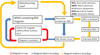 |
Fig. 1 Three recycling routes for REE permanent magnets from end-of-Life Waste Electrical & Electronic Equipments (WEEEs), adapted version from [3]. |
2 Current difficulties of permanent magnet disassembly
Recent magnet disassembly trials of PM electrical machines are investigated in this section. The purpose is to summarize the lessons in this field.
There were some well-known projects lunched in Europe since 2010 about rare earth magnets recycling, such as EREAN [5], RECVAL [6], MORE [7,8] and to the recent DEMETER [9]. Taking the project MORE (MOtor REcycling) for instance, it was led by Germany institute Fraunhofer ISI, and numerous industrial giants such as Siemens AG and Daimier AG. The project had explored several measurements of magnets disassembly from EoL traction motors of (H)EVs.
The EoL electrical machines they investigated were Surface mounted Permanent Magnet Synchronous Machine (SPMSM) and Interior Permanent Magnet Synchronous Machine (IPMSM), which are the mainstream radial flux PM electrical machines that had been widely used in (H)EVs. For the disassembly process of SPMSMs, thermal and chemical treatments have mainly been used. At thebeginning, the researchers attempted to directly use mechanical methods to remove the magnet from SPMSMs. However, it was found that the magnets can be easily damaged due to their brittleness and the inappropriate tools the researchers applied. Hence, the researchers switched to thermal treatments. The idea was to heat up the rotor in order to decompose the adhesive that used to fix the magnets. However, the problem appeared that the glue started to dissolve at 200 °C, while the demagnetized temperature for the NdFeB magnet is around 350 °C (different kinds of NdFeB magnets have different demagnetized temperature, but generally it should be higher than 300 °C). Thus, the individual magnet may uncontrollably fly out from the rotor due to the leftover magnetic forces. This might damage the magnet itself, as well as the heating stove. In this case, a temperature resistant fixation is required for the magnets. A heat resistance metal sleeve over the rotor surface was used by the researchers, as Figure 2 shows. Besides, the decomposition process of the glue can lead to heavy smoke. A more environment friendly extraction method for the decomposition products is therefore necessary. After the thermal treatment, complicated chemical treatments have to be implemented. In order to remove the leftover bandage and adhesive materials, some chemicals such as NaOH, boiling dimethylformamide and acetone need to be sprayed on the magnetssurface. However, the effect of the treatment was not always ideal. Contaminations of penetration adhesive were still found on the magnets under the microscope after thermal and chemical treatments.
For the disassembly process of IPMSMs, thermal and mechanical treatments have mainly been used. As the rotor consists of several skewed rings, the rotor needed to be separated into several pieces first. Then each piece was sent to furnaces for glue melting. Following as Figure 3 shown, punching and pressing devices are utilized to extract magnets. In order to prevent the damage caused by the attraction or repulsion forces of adjacent magnets, the magnets were forced to pass through separated tubes to a conveyor belt during the extraction. However, the feasibility of this method for real products is suspicious, as the magnets are not fully demagnetized, strong attractive forces between magnets and laminations still remain, it is very hard to directly push out magnets. Besides, many rotors also need resins casting during assembly process to make the structure robust. The fixation of resin can beextremely firm, it is almost impossible to remove it. How to solve this problem still left a question mark.
Therefore, according to the aforementioned magnet disassembly methods, researchers face several difficulties:
- 1.
High level of plant investment and long disassembly process. Such as complex magnet mechanical removal devices, heat-up stove, chemical treatment facilities. What worse, even if high investment has been made, it can only process very limit types of electrical machine. Once the techniques of electrical machine altered, the disassembly plant might no longer be valid. Thus, mass production will be an issue.
- 2.
Non-relevant aide materials, such as glue or plastic, cause additional cost. Besides, due to contamination or leaching from these aide materials, the recycling of the magnet is impeded. Moreover, the chemical treatments usually are health hazards. For instance, dimethylformamide has been classified in Group 2A carcinogen list by International Agency of Research on Cancer (IARC).
- 3.
NdFeB magnets are always brittle. However, there is no effective way to protect them from damages. Metal sleeve might not be enough for the protection. Moreover, the qualities of the magnets after disassembly remain unknown. For instance, Thermal treatment in air might make the surface of the magnet oxidize, even if there is a Nickel jacket on the surface of the magnet. Besides, thermal treatment may decrease the mechanical stiffness of NdFeB magnets. Regarding the magnet inserting process of IPMSM nowadays [10,11], there are many difficulties to pull out magnets without damage, such as the control of pull-out forces, glue removal, demagnetization and automation process.
- 4.
The magnets shape needs additional machining steps to fit in a new rotor design once the cavities shape changes. Although technically there is no difficulty to change the magnet shape by using cutting or spark erosion, it can increase the processing cost and time. Besides, for sintered NdFeB magnets, normally they are coated, even after their extraction from the machine. It will be a great difficulty to change the shape of the magnet with coating.
These difficulties must be carefully considered in the next phase electrical machine design. Thus, in order to find an ideal solution, alternative electrical machine designs and techniques have to be reviewed. The pros and cons of each type of electrical machine that related to magnets disassembly and recycling should be clearly known.
3 Design strategies for permanent magnets reuse
Here the main design strategies to be implemented for PM reuses have 3 different ways. They are complete magnet reusing, magnet segments reusing which so called “Lego” design and magnet powder reusing respectively.
3.1 Complete magnet reusing
The most straight forward way of reusing permanent magnets is to reuse the whole magnet piece, such as a magnet ring or magnet bulks. For instance, as [12] presented, the rotor is basically a magnet ring made by bonded NdFeB magnets. The magnet ring is magnetized as a continuous Halbach array, which makes the airgap flux sinusoidal concentrated. As for the reason of using bonded magnets instead of sintered magnets, it is mainly due to the high cost and large difficulties of magnetization for sintered magnets. Also unlike sintered magnets, which always need adhesive agent for fixing when they are segmented or the machine is for a high-speed application, bonded magnets do not require it, which results in easy extraction process.
The authors compared the results of the rotors with and without rotor iron back, it is found that due to the shield effect of Halbach array, the iron back has tiny influence on the motor electromagnetic performances, regardless of its mechanical function. Thus, the rotor can be simply a magnet ring and might be directly reused.
Thus, regarding the disassembly difficulties (see Sect. 2), difficulties 1 and 2 are possible to be solved on an industrial level. Difficulty 3 might be solved depending on the design of rotor bracket. However, difficulty 4 is still a problem – to reuse the ring for the next new motor design, it has no choice but to keep the rotor shape all the same. However, this is not always feasible in reality. So at the end, the magnet ring is always smashed for producing new magnet again, just as [13] illustrated.
Besides, there are some other issues regarding the machine design. The magnet ring designs can only be applied on few scenarios – in order to gain large airgap area and good mechanical strength, normally they are outer rotor design. To sufficiently take the advantages of Halbach array, it always goes to high pole number to obtain high flux concentration on the airgap. In this case, it is better to choose concentrated winding configurations. However, this combination leads to several issues – due to the high pole number, the top speed is limited to relatively low range. There is a high chance to induce large eddy current in the magnet ring due to high sub-harmonics [14]. Only if the resistivity of magnet is high, such as bonded magnet, or segmented magnets, the eddy current can be acceptable. Thus, there are huge limitations of applying magnet ring in electrical machines.
3.2 “Lego” design
The second way is magnet segments reusing, which is so called “Lego” design. It has more versatility comparing to the first method. As mentioned before, the common problem for magnet reuse is the different magnet shape with the iteration of machine generations. While with “Lego” design, this problem can be reasonably solved. As Figure 4 shown, from (a) to (d), a solid shaped magnet pole can be continuously divided into small and standardized segments. Thus, the small magnet segments can be reused for future generations, no matter what magnets shape they will be.
[15] exactly applied this idea on a SPMSM with NdFeB magnets for offshore wind turbine application. The magnet poles were not only segmented, but also be enclosed by a stainless steel container in order to prevent corrosion caused by the harsh environmentof the ocean. The main purpose of the paper was to investigate if the magnet reuse concept can change the electromagnetic performances of the wind turbine.
The magnet pole was assembled by standard magnet segments with adhesive agent. Although the active magnet space reduced due to the additional glue space, there is only a small reduction of torque and flux linkage. Therefore, the performances of wind turbine have almost no influence by the assembly method. In the paper, only around 5% axial length of the wind turbine was increased for the torque compensation. Besides, now as the shape of the magnet pole can be easily changed, the increased torque ripple and cogging torque which produced by the non-smooth surface of the magnet pole, can be easily cancelled byan appropriate pole shaping. Meanwhile magnet eddy current can be eliminated thanks to segmented magnets.
However, a huge limitation of this method is their costly assembly – massive adhesive agent need to be used, not to mention the strong repulsion forces between each segment when it is magnetized. Besides, as thermal treatments need to be used for disassembly, the magnet quality may be degraded. In this case, magnet coating is a vital consideration. [16] investigated this problem and found that not all magnet coatings of NdFeB magnets could sustain repeated thermal treatments. The authors compared 4 common coatings respectively: Zn, Epoxy, Ni-Cu-Ni and Ni-Cu+Epoxy. There were also 4 tests for each coating to go through: J–H curves measurements, pull-off test, corrosion test and microscopy check, after 1 and 5 heat cycles respectively. The results showed that no matter what coatings are, the J–H curves always kept the same after both 1 and 5 heating cycles, which means the remanence flux density Br and Coercivity Hc kept constant after heating. However, for pull-off test and corrosion test, Ni-Cu+Epoxy and Ni-Cu-Ni coatings had much better results than Zn and Epoxy coatings. Finally the authors concluded that Ni-Cu+Epoxy coating is the best choice to protect NdFeB magnets from thermal treatment, while Epoxy coating got the worst performance.
To summarize the points above, (see Sect. 2) difficulties 3 and 4 can be resolved, while difficulties 1 and 2 are still problems. Besides, regarding the machine design, normally “Lego” design is suit for SPM machine, either radial flux or axial flux. However, for electrical vehicle application, due to the requirements of high speed rotation, SPM machines are not always good candidates. Because SPM machine has some inherent disadvantages of low constant power speed range (CPSR) due to low saliencyand high normalized magnet flux linkage. These characteristics also contribute to large short circuit current, which leads to serious thermal issue. Besides, for radial flux inner rotor SPMSM, the magnets always need to be fixed by a sleeve made of titanium or carbon fiber, which is costly and performances may be degraded [17].
In summary, “Lego” design has many difficulties for mass production. It may only suitable for large PM electrical machines, such as wind turbine applications.
 |
Fig. 4 (a) A solid piece of bread loaf magnet. (b) Segmented bread loaf magnet. (c) Combined rectangular shape magnet. (d) Magnet pole with standard segments for reusing. |
3.3 Magnet powder reusing
Following the “Lego” concept, the magnet segment can be eventually divided into magnet powder. Thus, this is called magnet powder reusing. In fact, magnet powder materials are not rare at all – before magnets sintered or bonded, their states are just powder. Therefore, it is possible to directly make the magnet inside the rotor by special treatments. [18] developed a novel manufacturing method called IP1 magnet which pressing and sealing NdFeB magnet powder directly into a stainless steel container prior to magnetization, without any bind agent or coating. The advantages are obvious considering the random shape it is able to form, and glue-free production for easy extraction. While no matter how simply it looks to extract magnets, demagnetization is always the first step. Moreover the demagnetized chunks which taken out from the rotor still need to be mechanically crushed again. Thus, the authors investigated the recycled magnets quality after these thermal and mechanical treatments.
It was found that the temperature of demagnetization highly influenced the performance of the recycled magnet powder. The ideal demagnetizing temperature was 350 °C, which BH product after re-magnetizing was higher than the other two demagnetizing temperatures 400 °C and 650 °C. Nevertheless, no matter what the demagnetization temperature was, there was always around 10% reduction of Br and 20% reduction of Hc.
Notwithstanding, currently the direct magnet powder compression method is only for small motor applications (axial length < 5cm, outer diameter < 5cm). Demonstrations are needed for more powerful applications in the future, such as traction motors in (H)EVs.
[13] shows another possibility to realize magnet powder reusing – this is a new type of anisotropic Dysprosium free NdFeB magnet powder with thermoplastic binder. It can be recycled by mixing with a certain proportion of new magnet powder to maintain the magnet quality, as Figure 5 shows.
This magnet is feasible for EV applications due to promising flux density and coercivity – the energy product of the magnet is between Ferrite magnets and sintered NdFeB magnets. Besides, as this is a type of bonded magnet, any shape can be made. Thus, this is especially suitable for IPMSMs. It is even possible to directly inject the bonded magnet in colloid stateinto the rotor cavities during high temperature (injection molding). During this injection process, the magnets could be magnetized at the same time inside a rotor core. Thus, the rotor assembly process becomes also easier.
For the magnet extraction, the rotor can be heated up to Curie temperature Tc of the bonded magnets. As the melting point of the binder (PPS) is close to Tc, magnets can be melted and demagnetized at the same time, and then they can be easily removed from the rotor.
Thus, magnet powder reusing can solve the difficulties of 3 and 4. Once the assembly and disassembly process become standardized, the difficulty 1 will not be an issue. Besides, the magnet binder normally is non-toxic and environmental friendly. No other chemical treatment needs to be applied during the disassembly process. Thus, difficulty 2 is not a serious issue. Thus, this will be a promising method for magnet reuse and recycling.
In summary, the listed three strategies are only aiming at magnet reuse and recycling. In fact, there are some general methods for easy disassembly, which can naturally improve magnet disassembly rate. These general methods always refer to modular designs, such as [19,20]. However, a common challenge is the complex mechanical support needed for holding each module, no matter it is a joint or a bracket. Nevertheless, [21] had thoroughly reviewed the techniques of modular designs, so there is no need for repeatednarrative.
Also apart from physical measurement to extract magnets, there are some novel ways by using chemical treatment. For instance, Hydrogen Decrepitation (HD) is a promising solution for extracting magnet. As [22] demonstrated on hard disk drives, it is also possible to realize it on motor. Although it is called direct magnet recycling, due to additional process steps to recover magnets, it can be used on normal motors without special design for magnets disassembly. Thus, it becomes a very competitive method against motors with the concept of direct reuse.
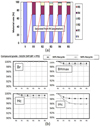 |
Fig. 5 Recycling experiment results, (a) percentage of different recycled magnet batches mixing for new magnet production (diagram of 30% recycled magnets), (b) performances of different mixed compound with 30% recycled magnet and 50% recycled magnet respectively [13]. |
4 Methodology of recyclability indexes
It is not enough to only think over new design methods for disassembly. It is also important to evaluate the recyclability between different machines.
The magnet recyclability can be mainly measured by two indexes. One index evaluates the recyclability from the views of assembly and disassembly of motors, considering their standardization and cost. The second index evaluates the impact of motor performances when applying recycled or reused magnets, considering energy consumptions over their usage life cycle. These two indexes together can be called Weighted Index of machines Recycling and Energy consumption (WIRE).
4.1 Weighted index of recycling and disassembly
The first index is introduced in [23]. The methodology is similar to Failure Mode and Effect Analysis (FMEA) process [24]. The results are obtained by the discussion of a group of experts and scored by their mutual agreement. Therefore, the index can be adjusted and even customized, depending on practical manufacturing conditions and experiences. However, the index is also well defined and goes into fine details level, such as components, materials and each process step. Therefore, the index can be seen as comprehensive and objective. A part of the scoring table is shown in Figure 6. In this table, there are two general columns – standard and cost. Standard means how common it is for a specific material or process. The more standardized, the higher the score, as it can simplify the recycling process. The meaning of cost is quite straightforward. It can be either a material cost or a process cost. However, bear in mind that the cost here is a relative concept. It does not indicate any real and absolute cost for a certain thing. For instance, a magnet cost in real life can be 50 €/kg, an iron cost in real life can be 5 €/kg. While in the table sheet, people always give 5 points to the magnet, while 1 point to the iron. Therefore, the scores are only meaningful when people compare different motors with the same assumptions and under the same scenarios.
Then, under the two general columns, there are always two categories that denote “S” and “I”. “S” stands for “Score”, which simply depends on the scale of the respective section. “I” stands for “Importance”, which decide the criticality of the item in terms of recyclability of the materials or the process for recycling. Finally, the product of “S” and“I”outputs the final point of the item. For instance, in the cost part, magnet material can be very expensive, so“S” is 5 points. While the weight of magnets is very small compared to other materials usage, so “I” is given to 1 point. Eventually, magnet section gains “5 points”. In the opposite, for iron material it might be cheap, so “S” is 1 point, while the weight of iron is very high and occupies the biggest portion of the machine weight, thus “I”gets 5 points. At the end iron also gains the same “5 points” as magnet. Apparently, these scorings need to base on real prices and weights data of machines, rather than simply guess or estimate.
In the paper, once defining all the assumptions of each material, component and process step, the authors used the index to compare four different motors for DEMETER project [9]. These four motors have implemented strategies of complete magnet ring reusing, modular design, magnet bulks reusing and magnet powder reusing respectively, as Figure 7 shows.
After scoring, it was found that (a) and (c) gained higher scores than (b) and (d). The main reason is due to more standard materials and processes used for (a) and (c), while less standard for (b) and (d). Therefore, it indicates from the other side that the methodology has its inherent limitation of innovation exclusion. Because high novel machine designs always need to use unusually materials and assembly process, which make the cost and manufacture difficulties higher. Finally, the advantages and disadvantages of different strategies are summarized in Table 1. The application scope means how widely the design strategy can be used in general motor designs.
 |
Fig. 7 (a) Outer rotor SPM motor with Halbach Ring, magnet is highlighted in orange color; (b) 3D flux hybrid motor with modular stator, magnets are placed in rotor between gear-shape iron plates; (c) magnet assisted claw pole motor (rotor), magnets are highlighted in green color; (d) IPMSM with direct magnet injection molding, magnets are “boomerang” shape. |
4.2 Weighted index of energy
The second index is mentioned in [25,26] respectively. This index reflects the relationship between saved cost from recycled magnets and increased cost from efficiency degradation. First of all, [27] validated the efficiency map between simulation and experiment. The validated motor was a hub motor normally used for the traction of scooters or mini urban cars, as Figure 8 shows. The experiment test bench is shown in Figure 9. After considering copper losses, core losses and mechanical losses, the total efficiency of the motor can be obtained. The authors concluded that the simulation results were well coincide with experiment results. Hence following the same simulation principles, [26] calculated the totally energy consumptions of the machines with virgin magnets and with recycled magnets respectively. To do the calculation, several presumptions need to be defined:
 |
Fig. 8 (a) Outer rotor and magnets of the hub motor; (b) inner stator of the hub motor. |
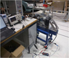 |
Fig. 9 Efficiency test bench with back-to-back configuration. |
- 1.
What are the physical parameters of the car for the motors traction, and how many motors in one car?
- 2.
What drive cycle need to be used, for instance, NEDC [28] or WLTP [29]? How many utilization hours in its life time?
- 3.
Within a drive cycle, are the braking periods, which equivalent to regenerative braking for EVs, considered? Are the efficiencies of other components, such as inverter, gearbox and battery, considered in the final results.
- 4.
What isthe performance of the recycled magnet?
- 5.
What are the prices of virgin and recycled magnets respectively, as well as electricity price?
In the paper, the motor was used for an urban pure electric vehicle with light weight and 50 km/h maximum speed. There were four identical motors that drive the car together. The urban part of NEDC drive cycle, which called ECE-15 drive cycle was applied, as the main project target was for European market. Also the torque and speed requirements of ECE-15 were well aligned with the performances of the motor. The total usage hours were assumed as 7300 h. Regenerative braking periods were not considered in the calculation and directly assumed as zero torque. Efficiencies of other components were not considered in the final results. The performances of recycled magnet were taken from [27], where Br of recycled sintered NdFeB magnets were 20% reduced comparing to the virgin magnets. Finally, the authors assumed a magnet prices matrix to cover a large scope of economic scenarios. The electricity price is taken as the average price of European countries electricity.
Moreover, in order to have a fair comparison, the envelopes of torque speed curve should be basically kept the same between machines with virgin magnets and machines with recycled magnets. To achieve this, the authors simply increased the axial length of the machine by 15%, as this is a practical way for normal radial flux SPM machines.
With the assumptions above, the calculations for efficiency maps of both machines, as well as final energy consumptions were done. With the energy consumptions of virgin and recycled machines, and with the prices of both magnets, the energy index can be created, as equation (1) shows
 (1)
(1)
where ECi is the energy cost index. Ec(j) is the energy cost of scenario j. Magc(j) is the magnet cost of scenario j. Ec(b) and Magc(b) are the indexes of a base scenario which calculated with virgin magnets usage. It was found that by applying recycled magnets, the motor even consumed a bit less energy during the whole usage life cycle. This may sound unreasonable. However, as the chosen motor is not dedicated to this drive cycle, and the authors have ignored the regenerative braking period, this result may happen. This from the other point of view proves how important it is to choose proper motor for different applications, instead of a common solution. For the energy index calculation, as currently the cost for recycled magnet is still an ongoing estimation, only assumptions for several scenarios can be made. For instance, an energy cost index matrix is shown in Figure 10.
When index equals to 1, it means the saved cost from magnets and extra cost from energy consumption can be balanced. So the smaller index is, the better the motor is for recycling. In Figure 10, the green region indicates positive economic effect for recycling. Conversely, the red region indicates negative economic effect.
Nevertheless, focusing on the urban car application, the authors claimed that it is totally possible to realize the recycledmagnets applications commercially. More importantly, this paper demonstrated a methodology for evaluating strategy of using recycled magnets in motors. Thus, depends on the aforementioned 5 assumptions, different applications may lead to different conclusions of the economic effect. Therefore, the index is prone to be a tool for helping people customize their own solution, instead of giving a certain conclusion. However, it has to be recognized that the degradation of coercivity in recycled magnets cannot be included in this index. This effect is hard to measure as it involves thermal issues. Thus, without fully redesign of the motor, coercivity degradation cannot be overcome.
[30] also discussed the possibility of commercialization for recycled NdFeB magnet used for electrical machines. The authors had similar opinions towards recycled magnets application with [13]. Besides, they found the superiorities of recycled NdFeB magnets over ferrite magnets used for the same motor. These superiorities included higher torque and higher efficiency, within similar demagnetization resistance.
Apart from simply cost estimation to measure the benefit of recycled magnets, there are other standard from professional Life Cycle Assessment (LCA) point of view, such as CO2 or pollutions reduction. For instance, [20] compared the global warming potential through life cycle assessment of NdFeB magnets. It is found that by doing magnet-to-magnet recycling, the total environmentfootprint can be significantly lower than using virgin magnets.
[31] hasdone similar LCA studies. But they much focused on different types of electrical machine and drive cycle than magnet recycling process.
They have also listed different scenarios depending on the 5 assumptions mentioned before. But the comparisons of magnets are between ferrite, SmCo and NdFeB. For the assumptions of machines, first, they need to provide the same peak torque and nearly the same peak power. Second, they need to have the same outer diameter, the same stator geometry and iron materials. Only the stack lengths can be varied, but the difference is within 10%. All these motors were used for an urban pure electric vehicle that has similar specifications with Nissan Leaf or VW e-Golf. For each motor, there was only one to drive the car. All these motors can push the car to 145 km/h maximum speed. Regenerative braking periods were taken into account in the calculation. Constant efficiencies of other components were also considered. Details of each material price in motors were well listed. Finally, there were 19 different drive cycles that involved in analyses, including ECE-15, NEDC and WLTP. They concluded that the motor with NdFeB magnets is the most compact and the most powerful. However, regarding both user phase and environmental impact of production, for most of drive cycles, NdFeB motor was given the worst credit. Interestingly, Ferrite magnet motor was given the highest credit on these aspects. But naturally, ferrite magnet motor is also the least compact and the weakest.
Thus [31] further indicates that it is necessary to find a kind of magnet that can compromise the results between machine power density and environmental impacts. In this case, using recycled NdFeB magnet could be the perfect compromise.
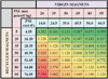 |
Fig. 10 Table sheet of energy cost index with assumed virgin magnets and recycled magnets costs. |
5 Conclusion
The study has summarized the recent literatures of magnet reuse and recycling strategies for electrical machines, as well as indexes for recyclability measurements and comparisons. It is found that different magnet reusing strategies need to be applied depend on different applications. Besides, theoretically it proves that, if magnets reusing can be considered in machine design phase, it can bring profit from the view of cost and energy saving. In the future, the collection and labor cost for end-of-life motors will be the other vital issues for the commercialization of magnet recycling applications. In fact, the study only introduces a small area of recycling strategies. From other prospects, like modular designs, or chemical treatments (i.e. Hydrogen Decrepitation process for NdFeB magnets), it can have a huge potential to enable easy and cheap routes of recycling rare earth permanent magnets from electrical machines.
Acknowledgements
The research leading to these results has received funding from European Community’s Horizon 2020 Programme ([H2020/2014-2019)] under Grant Agreement no. 674973 (MSCA-ETN DEMETER). This publication reflects only the authors view, exempting the Community from any liability. Project website: http://etn-demeter.eu/.
References
- K. Bourzac, The rare-earth crisis. MIT Technology Review. http://www.technologyreview.com/featuredstory/423730/the-rare-earth-crisis/ (2011) [Google Scholar]
- K. Binnemans, P.T. Jones, B. Blanpain, T. Van Gerven, Y. Yang, A. Walton, M. Buchert, J. Clean. Prod. 51, 1 (2013) [Google Scholar]
- Y. Yang, A. Walton, R. Sheridan, K. Güth, R. Gauβ, O. Gutfleisch, M. Buchert, B.M. Steenari, T. Van Gerven, P.T. Jones, K. Binnemans, J. Sustain. Metall. 3, 122 (2017) [CrossRef] [Google Scholar]
- H. Jin, P. Afiuny, S. Dove, G. Furlan, M. Zakotnik, Y. Yih, J.W. Sutherland, Environ. Sci. Technol. 52, 3796 (2018) [Google Scholar]
- EuropeanRare Earth (Magnet) Recycling Network, https://erean.eu/ [Google Scholar]
- innovative RE-use and reCycling VALue Chain for High-Power Magnets (RECVAL), http://www.agence-nationale-recherche.fr/Project-ANR-13-RMNP-0013/ [Google Scholar]
- U. Bast, F. Treffer, C. Thürigen, T. Elwert, F. Marscheider-Weidemann, Recycling von Komponenten und strategischen Metallen aus elektrischen Fahrantrieben, Recycling und Rohstoffe, Bd, vol 5, 2014 [Google Scholar]
- T. Klier, F. Risch, J. Franke, Disassembly, recycling, and reuse of magnet material of electric drives, Assembly and Manufacturing (ISAM), IEEE International Symposium, p. 88, 2013 [Google Scholar]
- European Training Network for the Design and Recycling of Rare-Earth Permanent Magnet Motors and Generators in Hybrid and Full Electric Vehicles (DEMETER), https://etn-demeter.eu/ [Google Scholar]
- J. Franke, B. Hofmann, J. Tremel, A. Meyer, Procedia CIRP 26, 724 (2015) [Google Scholar]
- J. Tremel, B. Hofmann, F. Risch, Adv. Mat. Res. 769, 3 (2013) [Google Scholar]
- A.K. Jha, L. Garbuio, A. Kedous-Lebouc, J.P. Yonnet, J.M. Dubus, Design and comparison of outer rotor bonded magnets Halbach motor with different topologies. In Electrical Machines, Drives and Power Systems ELMA, 15th IEEE. International Conference, p. 6, June, 2017 [Google Scholar]
- H. Matsuoka, Proposal of Dy-free Nd anisotropic bonded magnet and its new applied motors, 22th Magnetic Application Technology Symposium, A3-2-20, 2014 [Google Scholar]
- A.K. Jha, A. Kedous-Lebouc, L. Garbuio, J.P. Yonnet, J.M. Dubus, FEA based analysis on effect of slot pole combination on motor torque and magnet eddy current loss with bonded NdFeB Halbach rotor, In Electrical Machines and Systems (ICEMS), 20th International Conference, IEEE, p. 1, 2017 [Google Scholar]
- S. Hogberg, T.S. Pedersen, B.B. Jensen, N. Mijatovic, J. Holboll, Direct Reuse of Rare Earth Permanent Magnets -Wind Turbine Generator Case Study, In Electrical Machines (ICEM), 2016 XXII International Conference, p. 1625, 2016 [Google Scholar]
- S. Hogberg, J. Holboll, N. Mijatovic, B.B. Jensen, F.B. Bendixen, IEEE Trans. Magn. 53, 1 (2016) [Google Scholar]
- Z. Li, A. Kedous-Lebouc, R. Fratila, J. Legranger, J.M. Dubus, A. Ikram, Investigation on surface mounted PM machines with magnet recycling concept for hybrid electrical vehicle applications. In Electrical Machines and Systems, In Electrical Machines and Systems (ICEMS), 2017 20th International Conference, IEEE, p. 1, 2017 [Google Scholar]
- S. Högberg, F.B. Bendixen, N. Mijatovic, B.B. Jensen, J. Holb, Influence of demagnetization-temperature on magnetic performance of recycled Nd-Fe-B magnets, In Electric Machines & Drives Conference (IEMDC), IEEE, p. 1242, 2015 [Google Scholar]
- C. Henaux, B. Nogarede, D. Harribey, IEEE Trans. Magn. 48, 2035 (2012) [Google Scholar]
- T.J. Woolmer, M.D. McCulloch, Analysis of the yokeless and segmented armature machine, In Electric Machines & Drives Conference, IEMDC’07, IEEE International, 1, p. 704, 2007 [Google Scholar]
- Z.Q. Zhu, Y.X. Li, CES Trans. Electr. Mach. Syst. 2, 93 (2018) [Google Scholar]
- A. Walton, H. Yi, N. Rowson, J. Speight, V. Mann, R. Sheridan, A. Bradshaw, I. Harris, A. Williams, J. Clean. Prod. 104, 236 (2015) [Google Scholar]
- A.K. Jha, Z. Li, A.G. Gonzalez, P. Upadhayay, P.O. Rasmussen, A. Kedous-Lebouc, L. Garbuio, Weighted Index of Recycling and Energy Cost for motors in Electric Vehicles, International Symposium on Power Electronics, Electrical Drives, Automation and Motion (SPEEDAM), IEEE, p. 407, 2018 [Google Scholar]
- S.H. Teng, S.Y. Ho, Failure mode and effects analysis: an integrated approach for product design and process control, Int. J. Qual. Reliab. Manag. 13, 8 (1996) [CrossRef] [Google Scholar]
- A.G. Gonzalez, A.K. Jha, Z. Li, P. Upadhayay, P.O. Rasmussen, Validation of Efficiency Maps of an Outer Rotor Surface Mounted Permanent Magnet Machine for Evaluation of Recyclability of Magnets, presented at Intermag, 2018 [Google Scholar]
- P. Upadhayay, A.G. Gonzalez, Z. Li, A.K. Jha, P.O. Rasmussen, A. Kedous- Lebouc, J.C. Mipo, Evaluation of energy cost index for an electric vehicle motor over a particular drive cycle with recycled magnet concept, In Electrical Machines (ICEM), presented at XXIII International Conference, 2018 [Google Scholar]
- R.S. Sheridan, A.J. Williams, I.R. Harris, A. Walton, J. Magn. Magn. Mater. 350, 114 (2014) [Google Scholar]
- New European Driving Cycle (NEDC), https://en.wikipedia.org/wiki/New_European_Driving_Cycle [Google Scholar]
- Volkswagen, New standards for consumption values, https://www.volkswagen.com.mt/en/wltp.htmlhome [Google Scholar]
- M. Kimiabeigi, R.S. Sheridan, J.D. Widmer, A. Walton, M. Farr, B. Scholes, I.R. Harris, IEEE Trans. Ind. Electron. 65, 3795 (2018) [Google Scholar]
- E.A. Grunditz, S.T. Lundmark, M. Alatalo, T. Thiringer, A. Nordelöf, Three traction motors with different magnet materials–Influence on cost, losses, vehicle performance, energy use and environmental impact, In : Ecological Vehicles and Renewable Energies (EVER), Thirteenth International Conference on. IEEE, p. 1, 2018 [Google Scholar]
Cite this article as: Ziwei Li, Afef Kedous-Lebouc, Jean-Marc Dubus, Lauric Garbuio, Sophie Personnaz, Direct reuse strategies of rare earth permanent magnets for PM electrical machines – an overview study, Eur. Phys. J. Appl. Phys. 86, 20901 (2019)
All Tables
All Figures
|
Fig. 1 Three recycling routes for REE permanent magnets from end-of-Life Waste Electrical & Electronic Equipments (WEEEs), adapted version from [3]. |
| In the text | |
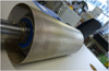 |
Fig. 2 The temperature resistance metal sleeve over rotor surface to fix magnets [7]. |
| In the text | |
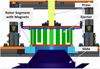 |
Fig. 3 Magnets dismantling concept of IPMSMs [7]. |
| In the text | |
|
Fig. 4 (a) A solid piece of bread loaf magnet. (b) Segmented bread loaf magnet. (c) Combined rectangular shape magnet. (d) Magnet pole with standard segments for reusing. |
| In the text | |
|
Fig. 5 Recycling experiment results, (a) percentage of different recycled magnet batches mixing for new magnet production (diagram of 30% recycled magnets), (b) performances of different mixed compound with 30% recycled magnet and 50% recycled magnet respectively [13]. |
| In the text | |
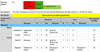 |
Fig. 6 Evaluation table sheet of materials section for standardization and cost scoring [23]. |
| In the text | |
|
Fig. 7 (a) Outer rotor SPM motor with Halbach Ring, magnet is highlighted in orange color; (b) 3D flux hybrid motor with modular stator, magnets are placed in rotor between gear-shape iron plates; (c) magnet assisted claw pole motor (rotor), magnets are highlighted in green color; (d) IPMSM with direct magnet injection molding, magnets are “boomerang” shape. |
| In the text | |
|
Fig. 8 (a) Outer rotor and magnets of the hub motor; (b) inner stator of the hub motor. |
| In the text | |
|
Fig. 9 Efficiency test bench with back-to-back configuration. |
| In the text | |
|
Fig. 10 Table sheet of energy cost index with assumed virgin magnets and recycled magnets costs. |
| In the text | |
Current usage metrics show cumulative count of Article Views (full-text article views including HTML views, PDF and ePub downloads, according to the available data) and Abstracts Views on Vision4Press platform.
Data correspond to usage on the plateform after 2015. The current usage metrics is available 48-96 hours after online publication and is updated daily on week days.
Initial download of the metrics may take a while.