| Issue |
Eur. Phys. J. Appl. Phys.
Volume 82, Number 3, June 2018
|
|
|---|---|---|
| Article Number | 31401 | |
| Number of page(s) | 4 | |
| Section | Review Article | |
| DOI | https://doi.org/10.1051/epjap/2018180201 | |
| Published online | 10 October 2018 | |
https://doi.org/10.1051/epjap/2018180201
Review Article
Towards an image-guided restricted drug release in friendly implanted therapeutics
GeePs − Group of Electrical Engineering − Paris, UMR CNRS 8507, CentraleSupélec, Univ. Paris-Sud, Université Paris-Saclay, Sorbonne Université, 3 and 11 rue Joliot-Curie, Plateau de Moulon,
91192
Gif-sur-Yvette Cedex, France
* e-mail: This email address is being protected from spambots. You need JavaScript enabled to view it.
Received:
3
July
2018
Received in final form:
24
July
2018
Accepted:
25
July
2018
Published online: 10 October 2018
Abstract
This review aims to expose a possible therapeutics scheme of using active implants for restricted drug release accounting for friendly wellbeing and security of patient. The review of embedded therapeutics, regulated drug administration, minimally-invasive issues and governing non-ionizing position detection suggested a possible MR image-guided approach. The magnetic resonance imaging is then investigated and its environmental compatibility is explored through electromagnetic compatibility analysis for embedded therapeutics.
© A. Razek, published by EDP Sciences, 2018
 This article is distributed under the terms of the Creative Commons Attribution License https://creativecommons.org/licenses/by/4.0 which permits unrestricted use, distribution, and reproduction in any medium, provided the original author(s) and source are credited.
1 Introduction
A topical major question embraces embedded therapeutics [1–7] by means of active locally constrained drug delivery technologies [8,9]. Such therapeutics structures might use active implant technologies. These technologies employ drug liberation systems for intra or bordering tissue overlaying a given zone. The materials used in these devices have been exploited to develop intelligent delivery media that can be injected locally as a fluid and ultimately transform into an appropriate drug depot by monitoring environmental parameters such as temperature, pH, ionic composition.
In implanted therapeutics, sociable comfort and safety of patient imply to use minimally-invasive techniques. Furthermore the treatment should be precisely constrained to the touched zone and the local release implant technology should handle non-destructive biological sensing.
These requirements of implanted therapeutics are first reviewed. Such review postulates to use the assistance of magnetic resonance imaging (MRI) technology.
The second part of the paper concerns the MR image-guided technology. First, the fields used in the MRI are examined and their environmental compatibility is analyzed. Then the biological effects versus the performance of such imagers are illustrated. Finally and based on this review, the impact of the presence of implants in MRI environment is studied through electromagnetic compatibility (EMC) analysis.
2 Requirements of implanted therapeutics
2.1 Minimally invasive technology
Well-being of the patient implies to use minimally invasive techniques. For implanted therapeutics this suggests the employment of biodegradable materials and wireless regulated actuation.
These technologies have been incarnated in a diversity of configurations as coatings, emollients, wafers, rods, and particles; they realize probable and sustained drug release kinetics. These mechanisms are generally biodegradable [10,11] in order to avoid an additional surgical for their removal and a returning immune reaction of the external object.
Wireless powering/control transmission involves energy and signals from an exterior device to the implant without physical contact [12]. This technology is used in many applications concerning a wide range of powers from micro watt to several hundreds of kilo watts [13]. In the case of embedded therapeutics this concerns the actuation of very small implants through induced fields by external emitters.
2.2 Locally restricted release
For friendly comfort of patient the treatment should be precisely constrained to the affected area [8,9,14]. Such accuracy is correlated to the exactness of the implant actuation and strongly related to its tracking resolution in the space. So, the suitable solution for such topological assessment is the image-guided detection of the implant position in the space. In such a case the imager, in addition to its role for on-line detection of the affected zone, it can track the drug release in the zone.
2.3 Interactive intelligent AI operation
From the considerations of Sections 2.1 and 2.2, the image guided procedure may consist of a cooperative system. This interactive system is composed of the imager, the implant and the external wireless powering/control device. Such a system may be operate autonomously if integrates an artificial intelligent AI algorithm. In this case, the system has to operate under the survey of the health care team.
2.4 Biomedical imaging
Principal imaging tools use either X-rays (computed tomography, fluoroscopy), sound (ultrasound), magnetism (MRI), or radioactive pharmaceutical products (nuclear medicine: SPECT, PET) to evaluate the existing state of an organ and can supervise a subject over time for diagnostic and therapeutic evaluation. Each of these issues is more or less suitable for a specified situation.
2.5 Non-ionizing imaging
In a situation of prolonged exposure to imager as therapeutic support, only MRI and ultrasound do not undergo the ionizing radiations critical weakness [15]. The ultrasound imager even if radiation free, it requires an acoustic window (without air or bones).
The local delivery implanted technology should manage non-destructive biological indifferent sensing. So, MR image-guided equipment seems to be an excellent universal sensing solution for implanted therapeutics.
3 MRI, magnetic fields and compatibility
MRI system exploits intense static magnetic field B0, field gradients and rapid evolution of radio frequency pulses B1 [16]. Figure 1 illustrates these field components. The couple of gradient coils shown in Figure 1b correspond to one axis; there are 3 couples for the 3D gradient field.
These different sorts of fields are employed in fashioning an image founded on resonance and are basic features of MRI processes.
The MR imager is very allergic to electromagnetic noise and to the presence of magnetic or conductive materials which can cause image deterioration unless observing some necessary operational precautions: conventional operation corrections.
The static field of an MRI B0 should be homogeneous. Rectification of imperfections of this field due to deficiencies in the electromagnet or to the existence of peripheral ferromagnetic little stuffs may be achieved by the adding of active shim coils or passive little steel parts. These coils are carrying a relatively small current and offer assisting fields to balance inhomogeneity in B0.
The gradient coils are designed to create a required field gradient (location dependent magnetic field). Appropriate design of the dimension and outline of the coils is required to generate a regulated and homogeneous 3D gradient.
The radio frequency wave B1 has a frequency identical to this of rotation of protons (Larmor frequency of protons) which is B0 – dependent and given by 42.5 MHz per tesla.
Since MRI uses rapidly changing magnetic fields B1 and gradient, eddy currents are always induced in nearby conductors whenever imaging is performed which originate undesirable time-varying gradients and shifts in the field B0. There are several methods to reduce the eddy currents consequences: e.g. break of possible current loops, gradients active shielding, etc.
Considering these conventional operation corrections, the inclusion of minor ferromagnetic or conductive pieces (nuts, screws, etc.) in the MRI could almost not disturb imaging.
In the general case, and aside from the conventional operation corrections, the introduction of noteworthy magnetic or conductive materials in the close environment of MRI could create electromagnetic noise. The MRI-compatibility is defined in relation to such environment.
So, in embedded therapeutics the implant is supposed to employ MRI-compatible materials and must utilize MRI-compatible actuation [15–25].
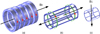 |
Fig. 1 MRI components: (a) electromagnet, (b) gradient coils (one couple for one axis), (c) radiofrequency coil. |
4 MRI performances versus biological effects
Although without radiation the MR imager operation must handle high performance and low biological effects. Each of the 3 fields employed in MRI system interrelates with the physical parameters of organic matters.
Perchance the safest one of the MRI magnetic fields is the static one. From the current literature, the only health risks notably related to the contact with B0 are linked to the existence of ferromagnetic stuffs or pacemakers in the body of patients.
The second probable source of risk of MRI fields is the pulsed field gradients. Due to the rising request for briefer cycles with greater temporal and spatial resolutions, the upgrading of modern gradient systems has led in the recent years to increase considerably the gradient output (strength and slew rate) which reduce imaging time. In spite of this, it is imperative to set proper thresholds for this gradient output to contain the appearance of unpleasant side effects for the patient. High output gradients engender a fluctuating electric field that may produce disagreeable peripheral nerve stimulation (PNS) and/or cardiac stimulation. These electric fields, if of sufficient strength and duration, can cause the excitation of the peripheral nervous system with characteristically spatially localized feelings of pressure, prickling, or muscle contracting. Nevertheless, PNS, which can be uncomfortable even if not dangerous to the patient, has a limit inferior than the intensity expected for probably life-threatening cardiac stimulation [26].
Radio frequency power accumulation corresponds to the furthermost danger for patient security in MRI exams. The specific absorption rate (SAR) operated in MRI examinations could be of 9 W/kg and for short enough duration so as producing less than 1 °C internal body temperature increase. A local rise in temperature of 1 °C in a healthy subject is completely out of danger; thus the MRI SAR levels are under the limits introduced by international security references.
This discussion shows that knowledge of the safety of MRI systems can help optimize both the safety and efficiency of system operation. Typical values characterizing the 3 different fields in MRI (Intensity, frequency and duration) [16] are given below:
-
B0: 0.2–7 T, 0 Hz, always present;
-
Gradient: 0–50 mT/m, 0–10 kHz, multiple pulses of few ms;
-
B1: 0–50 µT, 8–300 MHz, Amp. Mod. Pulses of few ms.
5 Electromagnetic compatibility (EMC) analysis
An important target of EMC analysis is to determine the impact of introducing in a complex system environment external materials and structures on the local distribution of electromagnetic field. Such impact permits to check the bounds of the system operation alteration.
In the case of MRI, EMC analysis aims to control the effect of hosting in the imager environment diverse substances and configurations used in embedded therapeutics. The results of such analysis permit the verification of the conventional operation corrections (see Sect. 3) and the optimization of materials and structures introduced in the MRI environment in order to fulfil the MRI-compatibility conditions.
5.1 Mathematical formulation
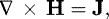
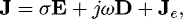
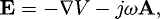
For EMC analysis different electromagnetic mathematical formulations could be considered [27]. The studied domain is often 3-D, the analyzed system may contain space heterogeneity [28] and the governing equations may need eddy currents computations in complex structures [29] where a suitable solution method can lead to the appropriate behavior. The basic full-wave electromagnetic formulation is given by:
 (1)
(1)
 (2)
(2)
 (3)
(3)
 (4)
where H and E are the magnetic and electric fields, B and D are the magnetic and electric inductions, A and V are the magnetic vector and electric scalar potentials. J and Je are the total and source current densities, σ is the electric conductivity and ω is the frequency pulsation. The magnetic and electric behavior laws respectively between B/H and D/E are characterized by the permeability µ and the permittivity ϵ.
(4)
where H and E are the magnetic and electric fields, B and D are the magnetic and electric inductions, A and V are the magnetic vector and electric scalar potentials. J and Je are the total and source current densities, σ is the electric conductivity and ω is the frequency pulsation. The magnetic and electric behavior laws respectively between B/H and D/E are characterized by the permeability µ and the permittivity ϵ.
The 3-D solution of the system (1–4) permits to determine in a system the perturbations in electromagnetic fields for a frequency pulsation accounting for external magnetic materials through the permeability, for eddy currents in external electric conductors through the electric conductivity and for displacement currents in external dielectrics through the permittivity [30].
5.2 EMC analysis in MRI environment
The analysis described in Section 5.1 could be achieved with the help of dedicated 3-D finite element model [13,18,19] of the MRI environment.
Considering a compensated homogeneous B0 and a controlled and uniform gradient as described in Section 3, the interaction of different hosted materials (corresponding to those constituting the embedded implant) in the MRI environment with the radio frequency magnetic field B1 could be investigated. Through such investigation the MRI compatibility could be verified or confirmed for a given material or a particular structure.
Under these conditions such EMC analysis permits the determination of the impact of the introduction of external objects in the MRI environment on the local 3-D distribution of the field B1 which is directly related to the image.
For given frequency pulsation and direction of the B1 field, such impact is determined by the material behavior laws (ϵ, µ, and σ) and the space orientation of structures [19].
Theoretically, the nearer these material behavior laws to those of free space (unity relative permeability and permittivity and zero conductivity) and the most reduced the conductor surfaces perpendicular to the field direction, this impact is minimized [30].
6 Conclusions
This paper underlined a possible strategy of using mobile implants for embedded therapeutics. Friendly therapeutics ought to use controlled drug release in minimally invasive and non-ionizing technique. The review of different issues illustrated that the aimed strategy may use non-ionizing image-guided drug release embedded implant which is powered and controlled wirelessly by an external source. The analysis of the principle biomedical imagers proposes the MR imager as the most adequate non-ionizing solution.
The review of MRI technology suggested an optimization of performance versus biological effects as well as of compatibility of hosted matters in its environment. Due to the aim for achieving such compatibility, an EMC analysis has been investigated accounting for the nature of different MRI fields and their conventional protections and corrections.
A possible future strategy would consist of an interactive system operating autonomously. Such a system is composed of the imager, the implant and its external wireless powering/control device. It integrates an AI algorithm and has to operate under the supervision of the health-care team.
References
- K. Bazaka, M.V. Jacob, Electronics 2, 1 (2013), DOI:10.3390/electronics2010001 [Google Scholar]
- A.B. Amar et al., Sensors 15, 28889 (2015), DOI:10.3390/s151128889 [CrossRef] [Google Scholar]
- A.K. Dash et al., J. Pharmacolog. Toxicolog. Methods 40, 1 (1998) [CrossRef] [Google Scholar]
- J. Perry et al., Curr. Oncol. 14, 189 (2007) [CrossRef] [PubMed] [Google Scholar]
- A.E.M. Eltorai et al., BioMed. Res. Int. 7 (2016), Article ID 1743472 [Google Scholar]
- R. Ramachandran et al., Sci. Rep. 7, 43271 (2017) DOI:10.1038/srep43271 [CrossRef] [PubMed] [Google Scholar]
- S. Mao et al., AIP Adv. 8, 056629 (2018) [Google Scholar]
- J. Okabe et al., Investig. Ophthalmol. Vis. Sci. 44, (2003) [Google Scholar]
- Y.H. Hsu et al., Int. J. Nanomed. 11, 3927 (2016) [CrossRef] [Google Scholar]
- Y.-H. Hsu et al., Int. J. Nanomed. 9, 4347 (2014) [CrossRef] [Google Scholar]
- Yan Peng, et al., Plos One 6, e22507 (2011) [CrossRef] [PubMed] [Google Scholar]
- Clementine Boutry, Biodegradable passive resonant circuits for wireless implant applications, Dissertation for the degree of Doctor of Sciences, Submitted to ETH Zurich, 2012 [Google Scholar]
- P.P. Ding et al., IEEE Trans. Magn. 50, 1037 (2014) [Google Scholar]
- J. Massiota et al., Lipid-porphyrin conjugates as potential multifunctional drug delivery system, International Symposium on Drug Discovery and New Therapeutics (Orsay, France, 2018) [Google Scholar]
- N.V. Tsekos et al., Annu. Rev. Biomed. Eng. 9, 351 (2007) [CrossRef] [PubMed] [Google Scholar]
- D.W. McRobbie, Br. J. Radiol. 85, 239 (2012) [Google Scholar]
- K. Chinzei et al., MR Compatibility of Mechatronic Devices: Design Criteria, MICCAI 1679, 1020–1030 (1999) [Google Scholar]
- R. Khairi et al., EMC analysis of MRI environment in view of optimized performance and cost of image-guided interventions, ISEF, Valencia (2015) [Google Scholar]
- Idem, Int. J. Appl. Electromagn. Mech. 51, S67 (2016) [CrossRef] [Google Scholar]
- Q. Su et al., Sensors 18, 810 (2018), DOI:10.3390/s18030810 [CrossRef] [Google Scholar]
- Y. Yun et al., Materialstoday 12, (2009) [Google Scholar]
- A. Khan et al., Sensors 16, 1172 (2016), DOI:10.3390/s16081172 [CrossRef] [Google Scholar]
- C. Dagdeviren et al., Extrem. Mech. Lett. 9, 269 (2016) [CrossRef] [Google Scholar]
- E. Lemair et al., Proc. Eng. 120, 360 (2015) [CrossRef] [Google Scholar]
- A. Stapleton et al., Appl. Phys. Lett. 111, 142902 (2017) [Google Scholar]
- J.A. Den Boer et al., J. Magn. Reson. Imag. 15, 520 (2002) [CrossRef] [Google Scholar]
- Z. Ren et al., IEEE Trans. Magn. 36, 751 (2000) [Google Scholar]
- O. Ouchetto et al., J. Mater. Process. Technol. 181, 225 (2007) [CrossRef] [Google Scholar]
- Z. Ren et al., IEE Proc. A (Phys. Sci. Meas.) 137, 135 (1990) [Google Scholar]
- Z.L. Wang, Mater. Today 20, 74 (2017) [CrossRef] [Google Scholar]
Cite this article as: Adel Razek, Towards an image-guided restricted drug release in friendly implanted therapeutics, Eur. Phys. J. Appl. Phys. 82, 31401 (2018)
All Figures
|
Fig. 1 MRI components: (a) electromagnet, (b) gradient coils (one couple for one axis), (c) radiofrequency coil. |
| In the text | |
Current usage metrics show cumulative count of Article Views (full-text article views including HTML views, PDF and ePub downloads, according to the available data) and Abstracts Views on Vision4Press platform.
Data correspond to usage on the plateform after 2015. The current usage metrics is available 48-96 hours after online publication and is updated daily on week days.
Initial download of the metrics may take a while.